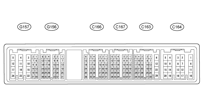
Terminal No. (Symbol)
| Wiring Color
| Terminal Description
| Condition
| Specified Condition
|
G157-23 (BATT) - C164-6 (E1)
| L - BR
| Battery (for measuring the battery voltage and for the ECM memory)
| Always
| 11 to 14 V
|
G156-24 (IGSW) - C164-6 (E1)
| B-O - BR
| Ignition switch
| Ignition switch ON
| 11 to 14 V
|
G157-24 (+B) - C164-6 (E1)
| B - BR
| Power source of ECM
| Ignition switch ON
| 11 to 14 V
|
G157-17 (+B2) - C164-6 (E1)
| B-R - BR
| Power source of ECM
| Ignition switch ON
| 11 to 14 V
|
G156-11 (MREL) - C164-6 (E1)
| W-G - BR
| MAIN relay
| Ignition switch ON
| 11 to 14 V
|
G156-11 (MREL) - C164-6 (E1)
| W-G - BR
| MAIN relay
| 30 seconds elapsed after ignition switch off
| 0 to 1.5 V
|
G156-6 (VCPA) - G156-5 (EPA)
| LG-R - BR-W
| Power source of accelerator pedal position sensor (for VPA)
| Ignition switch ON
| 4.5 to 5.5 V
|
G156-4 (VCP2) - G156-3 (EPA2)
| BR-R - BR-Y
| Power source of accelerator pedal position sensor (for VPA2)
| Ignition switch ON
| 4.5 to 5.5 V
|
G157-2 (VPA) - G156-5 (EPA)
| W-L - BR-W
| Accelerator pedal position sensor (for engine control)
| Ignition switch ON, accelerator pedal fully released
| 0.5 to 1.1 V
|
G157-2 (VPA) - G156-5 (EPA)
| W-L - BR-W
| Accelerator pedal position sensor (for engine control)
| Ignition switch ON, accelerator pedal fully depressed
| 3.0 to 4.6 V
|
G157-1 (VPA2) - G156-3 (EPA2)
| GR-G - BR-Y
| Accelerator pedal position sensor (for sensor malfunction detection)
| Ignition switch ON, accelerator pedal fully released
| 0.9 to 2.3 V
|
G157-1 (VPA2) - G156-3 (EPA2)
| GR-G - BR-Y
| Accelerator pedal position sensor (for sensor malfunction detection)
| Ignition switch ON, accelerator pedal fully depressed
| 3.4 to 5.0 V
|
C167-13 (VG) - C167-14 (EVG)
| W-R - B-W
| Mass air flow meter
| Idling
| Pulse generation
|
C167-7 (THA) - C167-1 (ETHA)
| Y-B - BR
| Intake air temperature sensor (built into mass air flow meter)
| Idling, intake air temperature at 20°C (68°F)
| 0.5 to 3.4 V
|
C167-10 (THIA) - C167-4 (ETHI)
| Y-G - BR
| Intake air temperature sensor
| Idling, intake air temperature at 0 to 80°C (32 to 176°F)
| 0.5 to 3.4 V
|
C167-9 (THW) - C167-3 (ETHW)
| R-L - BR
| Engine coolant temperature sensor
| Idling, engine coolant temperature at 80°C (176°F)
| 0.2 to 1.0 V
|
G157-6 (STA) - C164-6 (E1)
| L-Y - BR*1
B-Y - BR*2
| Starter signal
| Cranking
| 6.0 V or higher
|
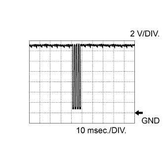
C166-21 (#1) - C164-6 (E1)
| B-W - BR
| No. 1 injector assembly
| Idling
| Pulse generation
(See waveform 2)
|
C166-22 (#2) - C164-6 (E1)
| R - BR
| No. 2 injector assembly
| Idling
| Pulse generation
(See waveform 2)
|
C166-23 (#3) - C164-6 (E1)
| V - BR
| No. 3 injector assembly
| Idling
| Pulse generation
(See waveform 2)
|
C166-24 (#4) - C164-6 (E1)
| Y-R - BR
| No. 4 injector assembly
| Idling
| Pulse generation
(See waveform 2)
|
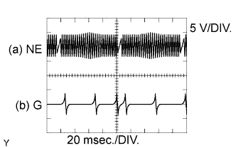
C163-13 (G+) - C163-14 (G-)
| Y - L
| Camshaft position sensor
| Idling
| Pulse generation
(See waveform 5)
|
C163-7 (NE+) - C163-8 (NE-)
| Y - L
| Crankshaft position sensor
| Idling
| Pulse generation
(See waveform 5)
|
G157-8 (STP) - C164-6 (E1)
| G-W - BR
| Stop light switch assembly
| Ignition switch ON, brake pedal depressed
| 7.5 to 14 V
|
G157-8 (STP) - C164-6 (E1)
| G-W - BR
| Stop light switch assembly
| Ignition switch ON, brake pedal released
| 0 to 1.5 V
|
G157-9 (ST1-) - C164-6 (E1)
| R-L - BR
| Stop light switch assembly
(opposite to STP)
| Ignition switch ON, brake pedal depressed
| 0 to 1.5 V
|
G157-9 (ST1-) - C164-6 (E1)
| R-L - BR
| Stop light switch assembly
(opposite to STP)
| Ignition switch ON, brake pedal released
| 7.5 to 14 V
|
C163-16 (CLSW)*1 - C164-6 (E1)
| G-W - BR
| Clutch switch assembly
| Ignition switch ON, clutch pedal released
| 8.5 to 14 V
|
G156-23 (TC) - C164-6 (E1)
| P-B - BR
| Terminal TC of DLC3
| Ignition switch ON
| 11 to 14 V
|
G157-19 (W) - C164-6 (E1)
| R-B - BR
| MIL
| MIL illuminated
| 0 to 3 V
|
G157-19 (W) - C164-6 (E1)
| R-B - BR
| MIL
| MIL not illuminated
| 11 to 14 V
|
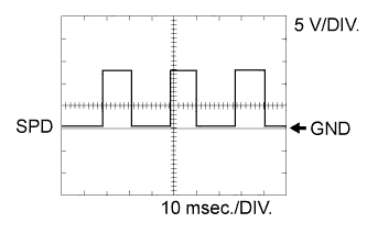
G156-30 (SPD) - C164-6 (E1)
| V-R - BR
| Speed signal from combination meter assembly
| Ignition switch ON, slowly wheel rotated
| Pulse generation
(See waveform 9)
|
C167-18 (VCPM) - C167-6 (EPIM)
| R-W - BR
| Power source of manifold absolute pressure sensor
| Ignition switch ON
| 4.5 to 5.5 V
|
C167-12 (PIM) - C167-6 (EPIM)
| L-B - BR
| Manifold absolute pressure sensor
| Negative pressure of 40 kPa (300 mmHg, 11.8 in.Hg) applied
| 0.1 to 0.7 V
|
C167-12 (PIM) - C167-6 (EPIM)
| L-B - BR
| Manifold absolute pressure sensor
| Same as atmospheric pressure
| 0.8 to 1.5 V
|
C167-12 (PIM) - C167-6 (EPIM)
| L-B - BR
| Manifold absolute pressure sensor
| Positive pressure of 170 kPa (1275 mmHg, 50.2 in.Hg) applied
| 1.6 to 2.3 V
|
G156-12 (IREL) - C164-6 (E1)
| B-W - BR
| EDU relay
| Idling
| 0 to 1.5 V
|
G157-18 (TACH) - C164-6 (E1)
| B-W - BR
| Engine speed
| Idling
| Pulse generation
|
C167-23 (ALT) - C164-6 (E1)
| G - BR
| Generator assembly (Alternator) duty ratio
| Idling
| Pulse generation
|
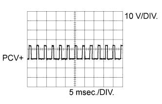
C163-23 (PCV+) - C163-12 (PCV-)
| G-W - G-Y
| Suction control valve
| Idling
| Pulse generation
(See waveform 1)
|
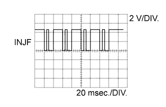
C166-20 (INJF) - C164-6 (E1)
| P - BR
| Injector driver
| Idling
| Pulse generation
(See waveform 3)
|
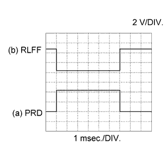
C166-19 (PRD) - C164-6 (E1)
| GR - BR
| Pressure discharge valve drive signal
| Engine warmed up, engine racing
| Pulse generation
(See waveform 4)
|
C167-24 (RLFF) - C164-6 (E1)
| GR - BR
| Pressure discharge valve confirmation signal
| Engine warmed up, engine racing
| Pulse generation
(See waveform 4)
|
C163-19 (IDLO) - C164-6 (E1)
| G - BR
| Injector Driver
| Idling
| 4 to 5.5 V
|
C166-18 (VIJ1) - C166-6 (EIJ1)
| B - R
| Power source of fuel pressure sensor (No. 1 injector assembly)
| Ignition switch ON
| 4.5 to 5.5 V
|
C166-12 (PIJ1) - C166-6 (EIJ1)
| W - R
| Fuel pressure sensor (No. 1 injector assembly)
| Engine warmed up, engine idling
| 1.4 to 1.7 V
|
C166-17 (VIJ2) - C166-5 (EIJ2)
| Y - L
| Power source of fuel pressure sensor (No. 2 injector assembly)
| Ignition switch ON
| 4.5 to 5.5 V
|
C166-11 (PIJ2) - C166-5 (EIJ2)
| G - L
| Fuel pressure sensor (No. 2 injector assembly)
| Engine warmed up, engine idling
| 1.4 to 1.7 V
|
C166-16 (VIJ3) - C166-4 (EIJ3)
| B - W
| Power source of fuel pressure sensor (No. 3 injector assembly)
| Ignition switch ON
| 4.5 to 5.5 V
|
C166-10 (PIJ3) - C166-4 (EIJ3)
| R - W
| Fuel pressure sensor (No. 3 injector assembly)
| Engine warmed up, engine idling
| 1.4 to 1.7 V
|
C166-15 (VIJ4) - C166-3 (EIJ4)
| L - Y
| Power source of fuel pressure sensor (No. 4 injector assembly)
| Ignition switch ON
| 4.5 to 5.5 V
|
C166-9 (PIJ4) - C166-3 (EIJ4)
| G - Y
| Fuel pressure sensor (No. 4 injector assembly)
| Engine warmed up, engine idling
| 1.4 to 1.7 V
|
C164-15 (M+) - C164-6 (E1)
| W - BR
| DC motor (turbocharger sub-assembly)
| Idling
| Pulse generation
(See waveform 6)
|
C164-14 (M-) - C164-6 (E1)
| B - BR
| DC motor (turbocharger sub-assembly)
| Idling
| Pulse generation
(See waveform 7)
|
C167-17 (VNVC) - C167-5 (VNE2)
| W - L
| Power source of nozzle vane position sensor
| Ignition switch ON
| 4.5 to 5.5 V
|
C167-11 (VNA) - C167-5 (VNE2)
| R - L
| Nozzle vane position sensor
| Ignition switch ON
| 2.3 to 2.7 V
|
C166-14 (VCVL) - C166-2 (EVLU)
| R-W - BR
| Power source of throttle position sensor
| Ignition switch ON
| 4.5 to 5.5 V
|
C166-8 (VLU) - C166-2 (EVLU)
| B- BR
| Throttle position sensor
| Ignition switch ON, throttle valve
fully opened
| 3.6 to 4.2 V
|
C166-8 (VLU) - C166-2 (EVLU)
| B- BR
| Throttle position sensor
| Ignition switch ON, throttle valve
fully closed
| 0.4 to 1.0 V
|
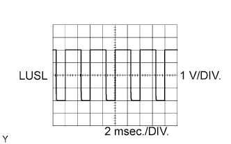
C163-17 (LUSL) - C164-6 (E1)
| GR - BR
| Diesel throttle duty signal
| Engine warmed up, racing engine
| Pulse generation
(See waveform 8)
|
C166-13 (VCEG) - C166-1 (EEGL)
| R-W - BR
| Power source of EGR valve position sensor
| Ignition switch ON
| 4.5 to 5.5 V
|
C166-7 (EGRA) - C166-1 (EEGL)
| R-Y - BR
| EGR valve position sensor
| Ignition switch ON
| 0.6 to 1.4 V
|
C164-1 (EGM+) - C164-13 (ME01)
| L - W-B
| EGR valve duty signal
| Engine warmed up, idling
| Pulse generation
|
C164-2 (EGM-) - C164-13 (ME01)
| Y - W-B
| EGR valve duty signal
| Engine warmed up, idling
| Pulse generation
|
C164-9 (ECBV) - C164-6 (E1)
| B-L - BR
| Vacuum switching valve (for EGR bypass valve)
| Vacuum switching valve assembly (for EGR bypass valve) on
| 0 to 1.5 V
|
Vacuum switching valve assembly (for EGR bypass valve) off
| 11 to 14 V
|
C164-7 (SCV) - C164-11 (E01)
| LG - W-B
| Vacuum switching valve (for No. 1 swirl control valve)
| Idling
| 0 to 1.5 V
|
Engine speed 2600 rpm or more
| 11 to 14 V
|
C164-8 (SCV2) - C164-11 (E01)
| W-L - W-B
| Vacuum switching valve (for No. 2 swirl control valve)
| Idling
| 0 to 1.5 V
|
Engine speed 2600 rpm or more
| 11 to 14 V
|
G156-10 (AC1) - C164-11 (E01)
| Y - W-B
| A/C signal
| A/C switch on
| 0 to 1.5 V
|
A/C switch off
| 11 to 14 V
|
G156-13 (ACT) - C164-11 (E01)
| R-L - W-B
| A/C signal
| Ignition switch ON
| 11 to 14 V
|
A/C cut control on
| 0 to 3 V
|
C163-26 (NSW)*2 - C164-11 (E01)
| L-Y - W-B
| Park/neutral position switch assembly
| Ignition switch ON, shift lever in P or N
| Below 3 V
|
Ignition switch ON, shift lever not in P or N
| 11 to 14 V
|
C163-16 (D)*2 - C164-11 (E01)
| G-Y - W-B
| Park/neutral position switch assembly
| Ignition switch ON, shift lever in D
| 11 to 14 V
|
Ignition switch ON, shift lever not in D
| Below 1 V
|
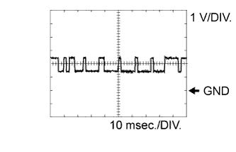
G156-36 (CANL) - C164-6 (E1)
| W - BR
| CAN communication line
| Ignition switch ON
| Pulse generation
(See waveform 10)
|
G156-35 (CANH) - C164-6 (E1)
| B - BR
| CAN communication line
| Ignition switch ON
| Pulse generation
(See waveform 11)
|
C163-18 (CAN-)*2 - C164-6 (E1)
| P - BR
| CAN communication line
| Ignition switch ON
| Pulse generation
(See waveform 10)
|
C163-24 (CAN+)*2 - C164-6 (E1)
| V - BR
| CAN communication line
| Ignition switch ON
| Pulse generation
(See waveform 11)
|
C167-22 (CINJ) - C164-6 (E1)
| B - BR
| INJ communication line
| Engine warmed up, idling
| Pulse generation
(See waveform 12)
|