Dtc P0818 Driveline Disconnect Switch Input Circuit
Drivetrain. Hilux. Tgn26, 36 Kun25, 26, 35, 36 Ggn25
DESCRIPTION
MONITOR DESCRIPTION
WIRING DIAGRAM
INSPECTION PROCEDURE
CHECK HARNESS AND CONNECTOR (NO. 2 TRANSFER INDICATOR SWITCH - BODY GROUND)
INSPECT NO. 2 TRANSFER INDICATOR SWITCH
CHECK HARNESS AND CONNECTOR (NO. 2 TRANSFER INDICATOR SWITCH - TCM)
DTC P0818 Driveline Disconnect Switch Input Circuit |
DESCRIPTION
The TCM detects the signal from the No. 2 transfer indicator switch (the transfer neutral position switch).This DTC indicates that the No. 2 transfer indicator switch remains on.DTC No.
| DTC Detection Conditions
| Trouble Area
|
P0818
| The No. 2 transfer indicator switch remains on while the vehicle is running under the following conditions for 30 seconds. (2-trip detection logic):
- Vehicle speed is 25.1 km/h (15.6 mph) or more.
- Transfer high and low shift lever position: H.
| - Short in No. 2 transfer indicator switch (the transfer neutral position switch) circuit
- No. 2 transfer indicator switch
- TCM
|
MONITOR DESCRIPTION
The TCM detects whether or not the transfer high and low shift lever is in neutral by monitoring the signal from the No. 2 transfer indicator switch.If the TCM detects that the transfer high and low shift lever is in neutral under the following conditions, the TCM will conclude that there is a malfunction of the No. 2 transfer indicator switch:- No. 2 transfer indicator switch indicates that the transfer high and low shift lever is in neutral.
- Transfer high and low shift lever is in the H position.
- The vehicle is traveling at 25.1 km/h (15.6 mph) or more.
- The No. 2 transfer indicator switch has been on for more than 30 seconds.
If all of the above conditions are detected, the TCM will conclude that there is a malfunction of the No. 2 transfer indicator switch, illuminate the MIL and store the DTC.
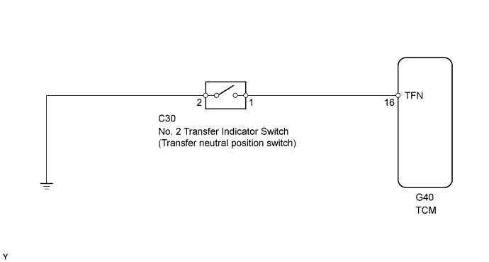
WIRING DIAGRAM
INSPECTION PROCEDURE
| 1.CHECK HARNESS AND CONNECTOR (NO. 2 TRANSFER INDICATOR SWITCH - BODY GROUND) |
Disconnect the No. 2 transfer indicator switch connector.
Measure the resistance according to the value(s) in the table below.
- Standard Resistance:
Tester Connection
| Condition
| Specified Condition
|
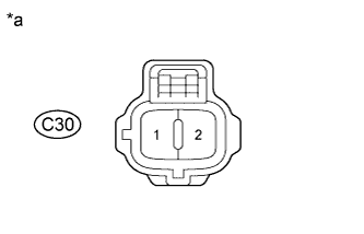
C30-2 - Body ground
| Always
| Below 1 Ω
|
Text in Illustration*a
| Front view of wire harness connector
(to No. 2 Transfer Indicator Switch)
|
| | REPAIR OR REPLACE HARNESS OR CONNECTOR |
|
|
| 2.INSPECT NO. 2 TRANSFER INDICATOR SWITCH |
Remove the No. 2 transfer indicator switch.
Measure the resistance according to the value(s) in the table below.
- Standard Resistance:
Tester Connection
| Switch Condition
| Specified Condition
|
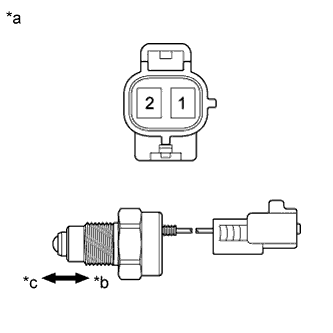
1 - 2
| Not pushed
| 10 kΩ or higher
|
1 - 2
| Pushed
| Below 1 Ω
|
Text in Illustration*a
| Component without harness connected
(No. 2 Transfer Indicator Switch)
|
*b
| Pushed
|
*c
| Not pushed
|
| 3.CHECK HARNESS AND CONNECTOR (NO. 2 TRANSFER INDICATOR SWITCH - TCM) |
Disconnect the C30 No. 2 transfer indicator switch connector.
Disconnect the G40 TCM connector.
Measure the resistance according to the value(s) in the table below.
- Standard Resistance:
Tester Connection
| Condition
| Specified Condition
|
C30-1 - G40-16 (TFN)
| Always
| Below 1 Ω
|
C30-1 or G40-16 (TFN) - Body ground
| Always
| 10 kΩ or higher
|
| | REPAIR OR REPLACE HARNESS OR CONNECTOR |
|
|