Navigation System Steering Pad Switch Circuit
DESCRIPTION
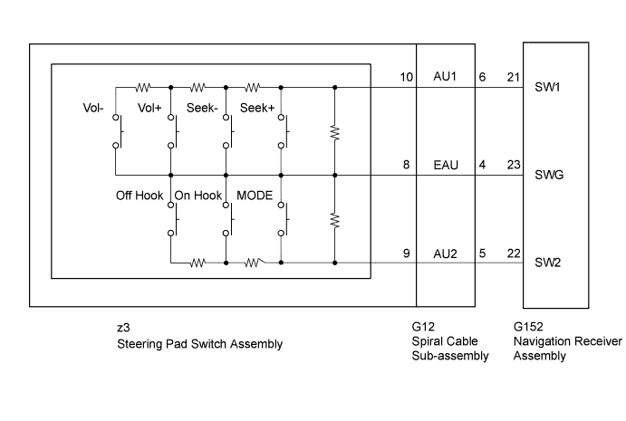
WIRING DIAGRAM
INSPECTION PROCEDURE
INSPECT STEERING PAD SWITCH ASSEMBLY
INSPECT SPIRAL CABLE SUB-ASSEMBLY
CHECK HARNESS AND CONNECTOR (NAVIGATION RECEIVER ASSEMBLY - SPIRAL CABLE SUB-ASSEMBLY)
NAVIGATION SYSTEM - Steering Pad Switch Circuit |
DESCRIPTION
This circuit sends an operation signal from the steering pad switch assembly to the navigation receiver assembly.If there is an open in the circuit, the navigation system cannot be operated using the steering pad switch assembly.If there is a short in the circuit, the same condition as when the switch is continuously depressed occurs.Therefore, the navigation receiver assembly cannot be operated using the steering pad switch assembly, and the navigation receiver assembly itself cannot function.
WIRING DIAGRAM
INSPECTION PROCEDURE
- CAUTION:
- The vehicle is equipped with an SRS (Supplemental Restraint System) which includes components such as airbags. Before servicing (including removal or installation of parts), be sure to read the precautionary notice for the SRS (HILUX_TGN26 RM000000KT10GEX.html).
| 1.INSPECT STEERING PAD SWITCH ASSEMBLY |
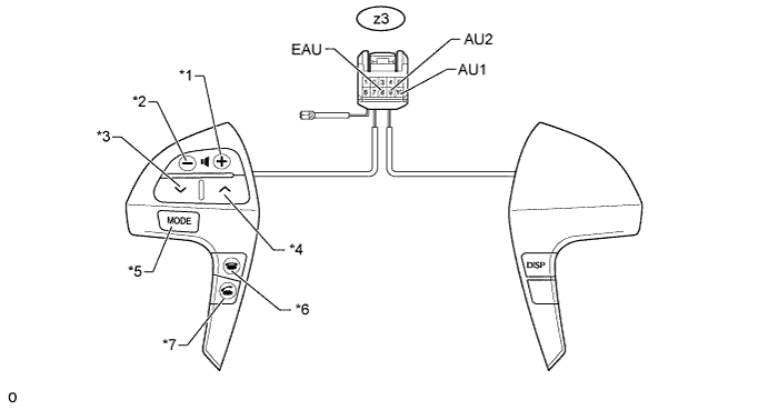
Remove the steering pad switch assembly (HILUX_TGN26 RM0000033RT08HX.html).
Text in Illustration*1
| Volume+ Switch
| *2
| Volume- Switch
|
*3
| Seek- Switch
| *4
| Seek+ Switch
|
*5
| MODE Switch
| *6
| On Hook Switch
|
*7
| Off Hook Switch
| -
| -
|
Measure the resistance according to the value(s) in the table below.
- Standard Resistance:
Tester Connection
| Switch Condition
| Specified Condition
|
z3-10 (AU1) - z3-8 (EAU)
| No switch is pushed
| 95 to 105 kΩ
|
Seek+ switch is pushed
| Below 2.5 Ω
|
Seek- switch is pushed
| 312.6 to 345.5 Ω
|
Volume+ switch is pushed
| 950 to 1050 Ω
|
Volume- switch is pushed
| 2954.5 to 3265.5 Ω
|
z3-9 (AU2) - z3-8 (EAU)
| No switch is pushed
| 95 to 105 kΩ
|
MODE switch is pushed
| Below 2.5 Ω
|
On Hook switch is pushed
| 312.6 to 345.5 Ω
|
Off Hook switch is pushed
| 950 to 1050 Ω
|
| 2.INSPECT SPIRAL CABLE SUB-ASSEMBLY |
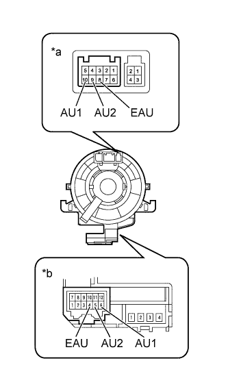
Remove the spiral cable sub-assembly (HILUX_TGN26 RM0000010B2012X.html).
Measure the resistance according to the value(s) in the table below.
- Standard Resistance:
Tester Connection
| Condition
| Specified Condition
|
8 (EAU) - 4 (EAU)
| Spiral cable is turned 2.5 rotations counterclockwise
| Below 1 Ω
|
Spiral cable is centered
|
Spiral cable is turned 2.5 rotations clockwise
|
10 (AU1) - 6 (AU1)
| Spiral cable is turned 2.5 rotations counterclockwise
|
Spiral cable is centered
|
Spiral cable is turned 2.5 rotations clockwise
|
9 (AU2) - 5 (AU2)
| Spiral cable is turned 2.5 rotations counterclockwise
|
Spiral cable is centered
|
Spiral cable is turned 2.5 rotations clockwise
|
Text in Illustration*a
| Steering Pad Switch Side
|
*b
| Vehicle Side
|
- CAUTION:
- The spiral cable is an important part of the SRS airbag system. Incorrect removal or installation of the spiral cable may prevent the airbag from deploying. Be sure to read the Precaution for the SRS (HILUX_TGN26 RM000000KT10GEX.html).
| 3.CHECK HARNESS AND CONNECTOR (NAVIGATION RECEIVER ASSEMBLY - SPIRAL CABLE SUB-ASSEMBLY) |
Disconnect the G152 navigation receiver assembly connector.
Disconnect the G12 spiral cable sub-assembly connector.
Measure the resistance according to the value(s) in the table below.
- Standard Resistance:
Tester Connection
| Condition
| Specified Condition
|
G152-21 (SW1) - G12-6 (AU1)
| Always
| Below 1 Ω
|
G152-22 (SW2) - G12-5 (AU2)
|
G152-23 (SWG) - G12-4 (EAU)
|
G152-21 (SW1) - Body ground
| Always
| 10 kΩ or higher
|
G152-22 (SW2) - Body ground
|
G152-23 (SWG) - Body ground
|
| | REPAIR OR REPLACE HARNESS OR CONNECTOR |
|
|