Power Door Lock Control System All Doors Cannot Be Locked / Unlocked Simultaneously
Door Lock. Hilux. Tgn26, 36 Kun25, 26, 35, 36 Ggn25
DESCRIPTION
WIRING DIAGRAM
INSPECTION PROCEDURE
CHECK POWER DOOR LOCK OPERATION
INSPECT POWER WINDOW REGULATOR MASTER SWITCH ASSEMBLY (DOOR CONTROL SWITCH)
CHECK HARNESS AND CONNECTOR (POWER WINDOW REGULATOR MASTER SWITCH - DRIVER SIDE JUNCTION BLOCK AND BODY GROUND)
INSPECT FRONT DOOR LOCK ASSEMBLY LH
CHECK SEAT BELT WARNING SYSTEM
CHECK HARNESS AND CONNECTOR (FRONT SEAT INNER BELT LH - FRONT DOOR LOCK LH)
CHECK HARNESS AND CONNECTOR (FRONT DOOR LOCK LH - DRIVER SIDE JUNCTION BLOCK AND BODY GROUND)
POWER DOOR LOCK CONTROL SYSTEM - All Doors cannot be Locked / Unlocked Simultaneously |
DESCRIPTION
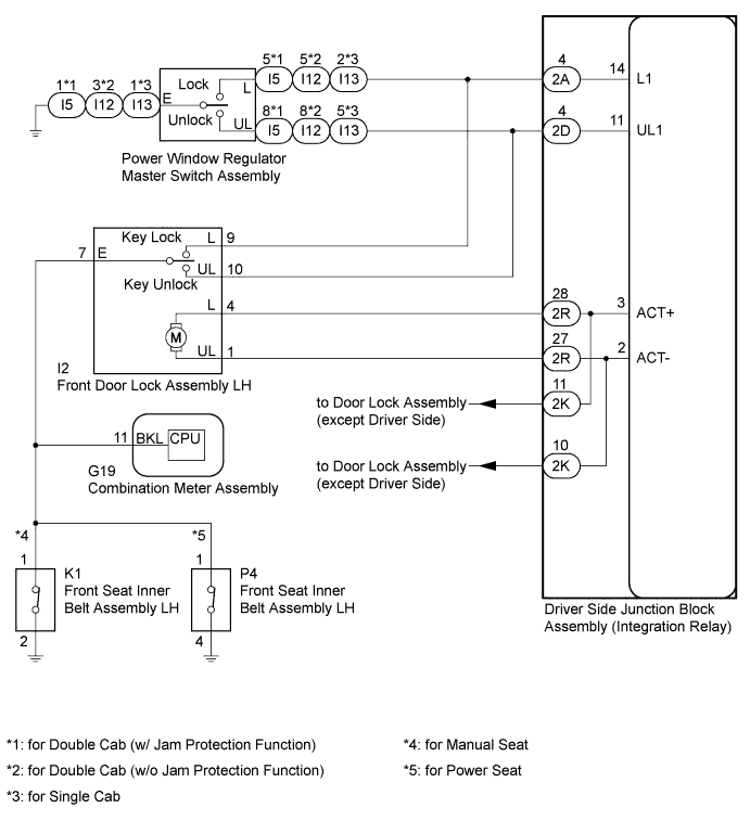
The driver side junction block assembly drives the door lock motors according to switch signals from the door control switch of the power window regulator master switch assembly and the driver side door key cylinder.However, the driver side door key-linked lock/unlock function will not operate when the driver side seat belt is fastened.
WIRING DIAGRAM
INSPECTION PROCEDURE
| 1.CHECK POWER DOOR LOCK OPERATION |
Check the power door lock operation.
ResultResult
| Proceed to
|
No doors can be locked using power window regulator master switch assembly (door control switch)
| A
|
No doors can be locked using key-linked switch
| B
|
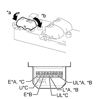
| 2.INSPECT POWER WINDOW REGULATOR MASTER SWITCH ASSEMBLY (DOOR CONTROL SWITCH) |
Remove the power window regulator master switch assembly (HILUX_TGN26 RM000002STU057X.html).
Measure the resistance according to the value(s) in the table below.
- Standard Resistance:
- for Double Cab (w/ Jam Protection Function):
Tester Connection
| Switch Condition
| Specified Condition
|
1 (E) - 5 (L)
| Lock
| Below 1 Ω
|
1 (E) - 5 (L), 1 (E) - 8 (UL)
| OFF
| 10 kΩ or higher
|
1 (E) - 8 (UL)
| Unlock
| Below 1 Ω
|
- for Double Cab (w/o Jam Protection Function):
Tester Connection
| Switch Condition
| Specified Condition
|
3 (E) - 5 (L)
| Lock
| Below 1 Ω
|
3 (E) - 5 (L), 3 (E) - 8 (UL)
| OFF
| 10 kΩ or higher
|
3 (E) - 8 (UL)
| Unlock
| Below 1 Ω
|
- for Single Cab:
Tester Connection
| Switch Condition
| Specified Condition
|
1 (E) - 2 (L)
| Lock
| Below 1 Ω
|
1 (E) - 2 (L) , 1 (E) - 5 (UL)
| OFF
| 10 kΩ or higher
|
1 (E) - 5 (UL)
| Unlock
| Below 1 Ω
|
Text in Illustration*A
| for Double Cab (w/ Jam Protection Function)
|
*B
| for Double Cab (w/o Jam Protection Function)
|
*C
| for Single Cab
|
*a
| Lock
|
*b
| Unlock
|
| 3.CHECK HARNESS AND CONNECTOR (POWER WINDOW REGULATOR MASTER SWITCH - DRIVER SIDE JUNCTION BLOCK AND BODY GROUND) |
Disconnect the I5*1, I12*2 or I13*3 power window regulator master switch assembly connector.
- *1: for Double Cab (w/ Jam Protection Function)
- *2: for Double Cab (w/o Jam Protection Function)
- *3: for Single Cab
Disconnect the 2A and 2D driver side junction block assembly connectors.
Measure the resistance according to the value(s) in the table below.
- Standard Resistance:
- for Double Cab (w/ Jam Protection Function):
Tester Connection
| Condition
| Specified Condition
|
I5-5 (L) - 2A-4 (L1)
| Always
| Below 1 Ω
|
I5-8 (UL) - 2D-4 (UL1)
| Always
| Below 1 Ω
|
I5-1 (E) - Body ground
| Always
| Below 1 Ω
|
I5-5 (L) or 2A-4 (L1) - Body ground
| Always
| 10 kΩ or higher
|
I5-8 (UL) or 2D-4 (UL1) - Body ground
| Always
| 10 kΩ or higher
|
- for Double Cab (w/o Jam Protection Function):
Tester Connection
| Condition
| Specified Condition
|
I12-5 (L) - 2A-4 (L1)
| Always
| Below 1 Ω
|
I12-8 (UL) - 2D-4 (UL1)
| Always
| Below 1 Ω
|
I12-3 (E) - Body ground
| Always
| Below 1 Ω
|
I12-5 (L) or 2A-4 (L1) - Body ground
| Always
| 10 kΩ or higher
|
I12-8 (UL) or 2D-4 (UL1) - Body ground
| Always
| 10 kΩ or higher
|
- for Single Cab:
Tester Connection
| Condition
| Specified Condition
|
I13-2 (L) - 2A-4 (L1)
| Always
| Below 1 Ω
|
I13-5 (UL) - 2D-4 (UL1)
| Always
| Below 1 Ω
|
I13-1 (E) - Body ground
| Always
| Below 1 Ω
|
I13-2 (L) or 2A-4 (L1) - Body ground
| Always
| 10 kΩ or higher
|
I13-5 (UL) or 2D-4 (UL1) - Body ground
| Always
| 10 kΩ or higher
|
| | REPAIR OR REPLACE HARNESS OR CONNECTOR |
|
|
| OK |
|
|
|
| REPLACE DRIVER SIDE JUNCTION BLOCK ASSEMBLY |
|
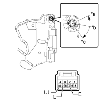
| 4.INSPECT FRONT DOOR LOCK ASSEMBLY LH |
Remove the front door lock assembly LH (HILUX_TGN26 RM00000138V01AX.html).
Measure the resistance according to the value(s) in the table below.
- Standard Resistance:
Tester Connection
| Switch Condition
| Specified Condition
|
7 (E) - 9 (L)
| Lock
| Below 1 Ω
|
7 (E) - 9 (L), 7 (E) - 10 (UL)
| Off
| 10 kΩ or higher
|
7 (E) - 10 (UL)
| Unlock
| Below 1 Ω
|
Text in Illustration*a
| Lock
|
*b
| Off
|
*c
| Unlock
|
| 5.CHECK SEAT BELT WARNING SYSTEM |
Turn the ignition switch to ON.
When the driver side seat belt is not fastened, check that the driver side seat belt warning light in the combination meter assembly blinks.
When the driver side seat belt is fastened, check that the driver side seat belt warning light in the combination meter assembly turns off.
- OK:
- Driver side seat belt warning light blinks and turns off according to above operation.
| 6.CHECK HARNESS AND CONNECTOR (FRONT SEAT INNER BELT LH - FRONT DOOR LOCK LH) |
Disconnect K1*1 or P4*2 front seat inner belt assembly LH connector.
- *1: for Manual Seat
- *2: for Power Seat
Disconnect the I2 front door lock assembly LH connector.
Measure the resistance according to the value(s) in the table below.
- Standard Resistance:
- for Manual Seat:
Tester Connection
| Condition
| Specified Condition
|
K1-1 - I2-7 (E)
| Always
| Below 1 Ω
|
K1-1 or I2-7 (E) - Body ground
| Always
| 10 kΩ or higher
|
- for Power Seat:
Tester Connection
| Condition
| Specified Condition
|
P4-1 - I2-7 (E)
| Always
| Below 1 Ω
|
P4-1 or I2-7 (E) - Body ground
| Always
| 10 kΩ or higher
|
| | REPAIR OR REPLACE HARNESS OR CONNECTOR |
|
|
| 7.CHECK HARNESS AND CONNECTOR (FRONT DOOR LOCK LH - DRIVER SIDE JUNCTION BLOCK AND BODY GROUND) |
Disconnect the I2 front door lock assembly LH connector.
Disconnect the 2A and 2D driver side junction block assembly connectors.
Measure the resistance according to the value(s) in the table below.
- Standard Resistance:
Tester Connection
| Condition
| Specified Condition
|
I2-10 (UL) - 2D-4 (UL1)
| Always
| Below 1 Ω
|
I2-9 (L) - 2A-4 (L1)
| Always
| Below 1 Ω
|
I2-7 (E) - Body ground
| Driver seat belt is not fastened
| Below 1 Ω
|
I2-10 (UL) or 2D-4 (UL1) - Body ground
| Always
| 10 kΩ or higher
|
I2-9 (L) or 2A-4 (L1) - Body ground
| Always
| 10 kΩ or higher
|
| | REPAIR OR REPLACE HARNESS OR CONNECTOR |
|
|
| OK |
|
|
|
| REPLACE DRIVER SIDE JUNCTION BLOCK ASSEMBLY |
|