Power Window Control System (W/ Jam Protection Function) Power Windows Do Not Operate At All
DESCRIPTION
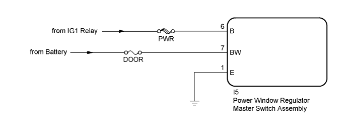
WIRING DIAGRAM
INSPECTION PROCEDURE
CHECK HARNESS AND CONNECTOR (POWER WINDOW REGULATOR MASTER SWITCH ASSEMBLY - BATTERY AND BODY GROUND)
POWER WINDOW CONTROL SYSTEM (w/ Jam Protection Function) - Power Windows do not Operate at All |
DESCRIPTION
If all of the power windows do not operate, the power window regulator master switch assembly may have no power or may be malfunctioning.
WIRING DIAGRAM
INSPECTION PROCEDURE
- NOTICE:
- Inspect the fuses for circuits related to this system before performing the following inspection procedure.
| 1.CHECK HARNESS AND CONNECTOR (POWER WINDOW REGULATOR MASTER SWITCH ASSEMBLY - BATTERY AND BODY GROUND) |
Disconnect the I5 power window regulator master switch assembly connector.
Measure the voltage according to the value(s) in the table below.
- Standard Voltage:
Tester Connection
| Condition
| Specified Condition
|
I5-7 (BW) - Body ground
| Always
| 11 to 14 V
|
I5-6 (B) - Body ground
| Ignition switch ON
| 11 to 14 V
|
Ignition switch off
| Below 1 V
|
Measure the resistance according to the value(s) in the table below.
- Standard Resistance:
Tester Connection
| Condition
| Specified Condition
|
I5-1 (E) - Body ground
| Always
| Below 1 Ω
|
Text in Illustration*a
| Front view of wire harness connector
(to Power Window Regulator Master Switch Assembly)
|
| | REPAIR OR REPLACE HARNESS OR CONNECTOR |
|
|