DESCRIPTION
MONITOR DESCRIPTION
MONITOR STRATEGY
CONFIRMATION DRIVING PATTERN
WIRING DIAGRAM
INSPECTION PROCEDURE
READ OUTPUT DTC
READ VALUE USING INTELLIGENT TESTER (OUTPUT VOLTAGE OF HEATED OXYGEN SENSOR)
PERFORM CONFIRMATION DRIVING PATTERN
CHECK WHETHER DTC OUTPUT RECURS (DTC P0130 IS OUTPUT AGAIN)
CONFIRM IF VEHICLE HAS RUN OUT OF FUEL IN PAST
CHECK PCV HOSE
INSPECT HEATED OXYGEN SENSOR
INSPECT NO. 1 INTEGRATION RELAY (MAIN) (POWER SOURCE VOLTAGE)
CHECK HARNESS AND CONNECTOR (HEATED OXYGEN SENSOR - ECM)
CHECK INTAKE SYSTEM
CHECK FUEL PRESSURE
INSPECT FUEL INJECTOR ASSEMBLY
DTC P0130 Oxygen Sensor Circuit Malfunction (Bank 1 Sensor 1) |
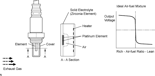
DESCRIPTION
The heated oxygen sensor is used to monitor oxygen concentration in the exhaust gas.The ECM uses the heated oxygen sensor information to regulate the air-fuel ratio and keep it close to the stoichiometric air-fuel ratio. This maximizes the ability of the Three-way Catalytic Converter (TWC) to purify the exhaust gases.The heated oxygen sensor generates an output voltage between 0.1 V and 0.9 V in response to the oxygen concentration in the exhaust gas.The heated oxygen sensor output voltage changes dramatically in the vicinity of the stoichiometric air-fuel ratio.If the oxygen concentration in the exhaust gas increases, the air-fuel ratio is lean and the heated oxygen sensor output voltage to the ECM drops below 0.45 V. If the oxygen concentration in the exhaust gas decreases, the air-fuel ratio is rich and the heated oxygen sensor output voltage to the ECM increases to above 0.45 V.The heated oxygen sensor is more efficient when heated. When the exhaust gas temperature is low, the sensor cannot generate useful voltage signals without supplementary heating. The ECM regulates the supplementary heating using a duty cycle approach to adjust the average current in the sensor heater element.DTC No.
| DTC Detection Condition
| Trouble Area
|
P0130
| Heated oxygen sensor output voltage is below 0.45 V for 75 seconds or more (1 trip detection logic).
| - Open or short in heated oxygen sensor (sensor 1) circuit
- Heated oxygen sensor (sensor 1)
- ECM
|
- HINT:
- The internal resistance of the heated oxygen sensor (sensor 1) cannot be measured using a tester.
- Sensor 1 refers to the sensor closer to the engine assembly.
- The output voltage of the heated oxygen sensor and the short-term fuel trim value can be read using the intelligent tester.
MONITOR DESCRIPTION
After the engine is started and the temperature of the heated oxygen sensor element is presumed to have reached the activation temperature, if the output from the heated oxygen sensor is below a set value, the system forces the air-fuel ratio to become rich. If the output from the heated oxygen sensor is below the threshold even after that, the ECM determines that there is a malfunction. The ECM then illuminates the MIL and stores a DTC.
MONITOR STRATEGY
Required Sensors/Components (Main)
| Heated oxygen sensor
|
Required Sensors/Components (Related)
| Engine coolant temperature sensor, Throttle position sensor, Crankshaft position sensor, Vehicle speed sensor
|
Frequency of Operation
| Once per driving cycle
|
CONFIRMATION DRIVING PATTERN
This confirmation driving pattern is used in the "Perform Confirmation Driving Pattern" step of the following diagnostic troubleshooting procedure.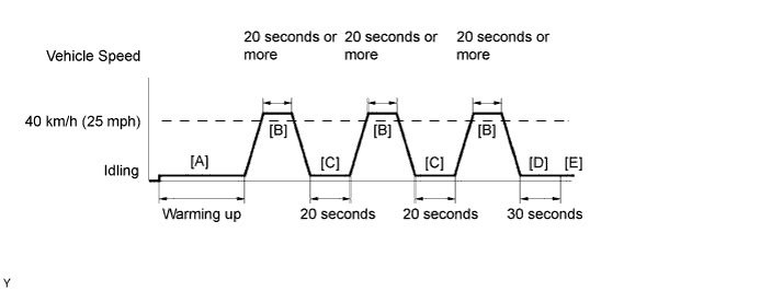
- Connect the intelligent tester to the DLC3.
- Turn the ignition switch to ON.
- Turn the intelligent tester on.
- Clear the DTCs (even if no DTCs are stored, perform the clear DTC operation).
- Turn the ignition switch off and wait for at least 30 seconds.
- Turn the ignition switch to ON and turn the intelligent tester on.
- Start the engine and warm it up until the engine coolant temperature reaches 75°C (167°F) or higher [A].
- Drive the vehicle at 40 km/h (25 mph) or more for 20 seconds or more [B].
- CAUTION:
- When performing the confirmation driving pattern, obey all speed limits and traffic laws.
- Let the engine idle for 20 seconds or more [C].
- Repeat steps [B] and [C] above at least 3 times in one driving cycle.
- Let the engine idle for 30 seconds or more [D].
- Enter the following menus: Powertrain / Engine and ECT / DTC [E].
- Read the pending DTCs.
- HINT:
- If a pending DTC is output, the system is malfunctioning.
- If a pending DTC is not output, perform the following procedure.
- Enter the following menus: Powertrain / Engine and ECT / Utility / All Readiness.
- Input the DTC: P0130.
- Check the DTC judgment result.
Intelligent Tester Display
| Description
|
NORMAL
| - DTC judgment completed
- System normal
|
ABNORMAL
| - DTC judgment completed
- System abnormal
|
INCOMPLETE
| - DTC judgment not completed
- Perform driving pattern after confirming DTC enabling conditions
|
N/A
| - Unable to perform DTC judgment
- Number of DTCs which do not fulfill DTC preconditions has reached ECU memory limit
|
- HINT:
- If the judgment result shows NORMAL, the system is normal.
- If the judgment result shows ABNORMAL, the system has a malfunction.
- If the judgment result shows INCOMPLETE or N/A, perform steps [B] through [E] again.
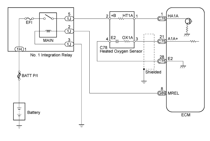
WIRING DIAGRAM
INSPECTION PROCEDURE
- HINT:
- Read freeze frame data using the intelligent tester. Freeze frame data records the engine conditions when malfunctions are detected. When troubleshooting, freeze frame data can help determine if the vehicle was moving or stationary, if the engine was warmed up or not, if the air-fuel ratio was lean or rich, and other data from the time the malfunction occurred.
Connect the intelligent tester to the DLC3.
Enter the following menus: Powertrain / Engine and ECT / DTC.
Read the DTCs.
ResultResult
| Proceed to
|
DTC P0130 is output
| A
|
DTC P0130 and other DTCs are output
| B
|
- HINT:
- If any DTCs other than P0130 are output, perform troubleshooting for those DTCs first.
| 2.READ VALUE USING INTELLIGENT TESTER (OUTPUT VOLTAGE OF HEATED OXYGEN SENSOR) |
Connect the intelligent tester to the DLC3.
Start the engine and turn the intelligent tester ON.
Enter the following menus: Powertrain / Engine and ECT / Data List / O2S B1S1.
Warm up the heated oxygen sensor at an engine speed of 2500 rpm for approximately 90 seconds.
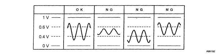
Read the output voltage of the heated oxygen sensor during engine idling.
- Standard:
- Fluctuates between less than 0.4 V and more than 0.6 V (see the following figure).
| 3.PERFORM CONFIRMATION DRIVING PATTERN |
Drive the vehicle in accordance with the driving pattern described in Confirmation Driving Pattern.
| 4.CHECK WHETHER DTC OUTPUT RECURS (DTC P0130 IS OUTPUT AGAIN) |
Connect the intelligent tester to the DLC3.
Turn the intelligent tester on.
Enter the following menus: Powertrain / Engine and ECT / Utility / All Readiness.
Input DTCs: P0130.
Check that the DTC monitor is NORMAL. If the DTC monitor is INCOMPLETE, perform the drive pattern again but increase the vehicle speed.
ResultDisplay (DTC Output)
| Proceed to
|
NORMAL
(No DTC output)
| A
|
ABNORMAL
(P0130 output)
| B
|
| 5.CONFIRM IF VEHICLE HAS RUN OUT OF FUEL IN PAST |
Has the vehicle run out of fuel in the past?
| YES |
|
|
|
| DTC CAUSED BY RUNNING OUT OF FUEL |
|
Check the PCV hose connections (HILUX_TGN26 RM000001I6600PX_01_0001.html).
- OK:
- PCV hose is connected correctly and is not damaged.
| | REPAIR OR REPLACE VENTILATION HOSE |
|
|
| 7.INSPECT HEATED OXYGEN SENSOR |
Inspect the heated oxygen sensor (HILUX_TGN26 RM000001421012X.html).
| 8.INSPECT NO. 1 INTEGRATION RELAY (MAIN) (POWER SOURCE VOLTAGE) |
Remove the No. 1 integration relay from the engine room relay block and junction block.
Measure the voltage according to the value(s) in the table below.
- Standard Voltage:
Tester Connection
| Condition
| Specified Condition
|
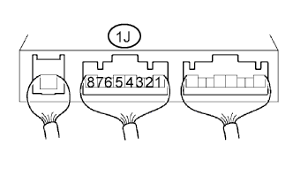
1J-5 - Body ground
| Ignition switch ON
| 11 to 14 V
|
| 9.CHECK HARNESS AND CONNECTOR (HEATED OXYGEN SENSOR - ECM) |
Disconnect the heated oxygen sensor connector.
Disconnect the ECM connector.
Measure the resistance according to the value(s) in the table below.
- Standard Resistance:
Tester Connection
| Condition
| Specified Condition
|
C78-1 (HT1A) - C75-1 (HA1A)
| Always
| Below 1 Ω
|
C78-3 (OX1A) - C75-21 (A1A+)
| Always
| Below 1 Ω
|
C78-4 (E2) - Body ground
| Always
| Below 1 Ω
|
C78-1 (HT1A) or C75-1 (HA1A) - Body ground
| Always
| 10 kΩ or higher
|
C78-3 (OX1A) or C75-21 (A1A+) - Body ground
| Always
| 10 kΩ or higher
|
| | REPAIR OR REPLACE HARNESS OR CONNECTOR |
|
|
Check the intake system for vacuum leakage (HILUX_TGN26 RM000001A3W024X_01_0008.html).
- OK:
- No leakage from intake system.
| | REPAIR OR REPLACE INTAKE SYSTEM |
|
|
Check the fuel pressure (HILUX_TGN26 RM000000YL704TX_01_0002.html).
| | REPAIR OR REPLACE FUEL SYSTEM |
|
|
| 12.INSPECT FUEL INJECTOR ASSEMBLY |
Check the fuel injector assembly (whether fuel volume is high or low, and whether injector pattern is poor) (HILUX_TGN26 RM000000WQQ076X.html).