Dtc B2780 Push Switch / Key Unlock Warning Switch Malfunction
DESCRIPTION
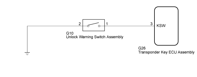
WIRING DIAGRAM
INSPECTION PROCEDURE
CLEAR DTC
CHECK FOR DTC
INSPECT UNLOCK WARNING SWITCH ASSEMBLY
CHECK HARNESS AND CONNECTOR (UNLOCK WARNING SWITCH - TRANSPONDER KEY ECU AND BODY GROUND)
DTC B2780 Push Switch / Key Unlock Warning Switch Malfunction |
DESCRIPTION
This DTC is stored if the transponder key ECU assembly does not detect that the unlock warning switch assembly is on even when the ignition switch is ON. Under normal conditions, the unlock warning switch assembly is on when the ignition switch is ON.DTC Code
| DTC Detection Condition
| Trouble Area
| DTC Output Confirmation Operation
|
B2780
| The unlock warning switch assembly is not detected as being on when the ignition switch is ON (1 trip detection logic*).
| - Unlock warning switch assembly
- Harness or connector
- Transponder key ECU assembly
| Insert the key into the ignition key cylinder.
|
- *: Only output while a malfunction is present.
Vehicle Condition and Fail-safe Operation when Malfunction DetectedVehicle Condition when Malfunction Detected
| Fail-safe Operation when Malfunction Detected
|
Engine cannot be started.
| -
|
Related Data List and Active TestDTC Code
| Data List and Active Test
|
B2780
| Key SW
|
WIRING DIAGRAM
INSPECTION PROCEDURE
- NOTICE:
- When replacing the transponder key ECU assembly, refer to the Service Bulletin.
- After performing repairs, perform the operation that fulfills the DTC output confirmation operation, and then confirm that no DTCs are output again.
Clear the DTCs (HILUX_TGN26 RM000000Z3I00TX.html).
Check for DTCs (HILUX_TGN26 RM000000Z3I00TX.html).
- OK:
- DTC B2780 is not output.
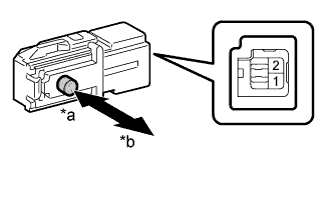
| 3.INSPECT UNLOCK WARNING SWITCH ASSEMBLY |
Remove the unlock warning switch assembly (HILUX_TGN26 RM000002ZQ6038X.html).
Measure the resistance according to the value(s) in the table below.
- Standard Resistance:
Tester Connection
| Switch Condition
| Specified Condition
|
1 - 2
| Pushed
| Below 1 Ω
|
Not pushed
| 10 kΩ or higher
|
Text in Illustration*a
| Pushed
|
*b
| Not pushed
|
| 4.CHECK HARNESS AND CONNECTOR (UNLOCK WARNING SWITCH - TRANSPONDER KEY ECU AND BODY GROUND) |
Disconnect the G10 unlock warning switch assembly connector.
Disconnect the G26 transponder key ECU assembly connector.
Measure the resistance according to the value(s) in the table below.
- Standard Resistance:
Tester Connection
| Condition
| Specified Condition
|
G10-1 - G26-3 (KSW)
| Always
| Below 1 Ω
|
G10-1 or G26-3 (KSW) - Body ground
| Always
| 10 kΩ or higher
|
G10-2 - Body ground
| Always
| Below 1 Ω
|
| | REPAIR OR REPLACE HARNESS OR CONNECTOR |
|
|
| OK |
|
|
|
| REPLACE TRANSPONDER KEY ECU ASSEMBLY |
|