Airbag System Tc And Cg Terminal Circuit
DESCRIPTION
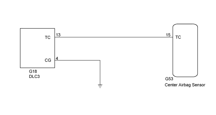
WIRING DIAGRAM
INSPECTION PROCEDURE
CHECK HARNESS AND CONNECTOR (DLC3 - CENTER AIRBAG SENSOR AND BODY GROUND)
AIRBAG SYSTEM - TC and CG Terminal Circuit |
DESCRIPTION
DTC output mode is set by connecting terminals TC and CG of the DLC3. The DTCs are communicated through SRS warning light blinking patterns.- HINT:
- When one or more of the warning lights blink continuously, the cause may be a ground short in the wiring of terminal TC of the DLC3 or an internal ground short in an ECU.
WIRING DIAGRAM
INSPECTION PROCEDURE
- NOTICE:
- After turning the ignition switch off, waiting time may be required before disconnecting the cable from the battery terminal. Therefore, make sure to read the disconnecting the cable from the battery terminal notice before proceeding with work (HILUX_TGN26 RM000004QR1006X.html).
- When disconnecting the cable from the negative (-) battery terminal while performing repairs, some systems need to be initialized after the cable is reconnected (HILUX_TGN26 RM000004QR300CX.html).
| 1.CHECK HARNESS AND CONNECTOR (DLC3 - CENTER AIRBAG SENSOR AND BODY GROUND) |
Turn the ignition switch off.
Disconnect the cable from the negative (-) battery terminal, and wait for at least 90 seconds.
Disconnect the G53 connector from the center airbag sensor.
Measure the resistance according to the value(s) in the table below.
- Standard Resistance:
Tester Connection
| Condition
| Specified Condition
|
G18-13 (TC) - G53-15 (TC)
| Always
| Below 1 Ω
|
G18-4 (CG) - Body ground
| Always
| Below 1 Ω
|
G53-15 (TC) - Body ground
| Always
| 1 MΩ or higher
|
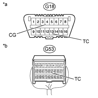
Text in Illustration*a
| Front view of DLC3
|
*b
| Rear view of wire harness connector
(to Center Airbag Sensor)
|
| | REPAIR OR REPLACE HARNESS OR CONNECTOR |
|
|