INSTALL DRIVE PLATE AND RING GEAR SUB-ASSEMBLY (for Automatic Transmission)
INSPECT AND ADJUST CLUTCH COVER ASSEMBLY (for Manual Transmission)
INSTALL MANUAL TRANSMISSION UNIT ASSEMBLY (for Manual Transmission)
INSTALL PROPELLER SHAFT WITH CENTER BEARING ASSEMBLY (for 4WD)
INSTALL PROPELLER SHAFT WITH CENTER BEARING ASSEMBLY (for Pre-Runner)
INSTALL COOLER COMPRESSOR ASSEMBLY (w/ Air Conditioning System)
ADD AUTOMATIC TRANSMISSION FLUID (for Automatic Transmission)
INSPECT AUTOMATIC TRANSMISSION FLUID (for Automatic Transmission)
Engine Assembly -- Installation |
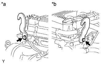
| 1. INSTALL ENGINE HANGER |
Install 2 engine hangers with 2 bolts.
- Torque:
- 42 N*m{428 kgf*cm, 31 ft.*lbf}
Text in Illustration *a Rear Side *b Front Side - HINT:
No. 1 Engine Hanger 12281-0C010 Bolt 90105-T0129
 |
| 2. REMOVE ENGINE FROM ENGINE STAND |
Attach an engine sling device and hang the engine with a chain block.
- NOTICE:
- Pay attention to the angle of the sling device as the engine assembly or engine hangers may be damaged or deformed if the angle is incorrect.
Lift the engine and remove it from the engine stand.
- NOTICE:
- With the exception of installing the engine assembly to an engine stand or removing the engine assembly from an engine stand, do not perform any work on the engine while it is suspended, as doing so is dangerous.
Place the engine onto a workbench.
| 3. INSTALL ENGINE ASSEMBLY |
Attach the engine sling device and chain block to the engine hangers.
Text in Illustration 
Lower
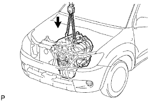 |
Slowly lower the engine assembly into the engine compartment.
Install the engine mounting brackets with the 4 bolts and 4 nuts.
- Torque:
- 38 N*m{388 kgf*cm, 28 ft.*lbf}
Remove the 2 bolts and 2 engine hangers.
| 4. INSTALL REAR END PLATE |
Install the end plate with the bolt.
- Torque:
- 18 N*m{184 kgf*cm, 13 ft.*lbf}
Connect the No. 1 water by-pass pipe to the rear end plate with the bolt.
- Torque:
- 18 N*m{178 kgf*cm, 13 ft.*lbf}
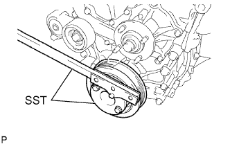
| 5. INSTALL DRIVE PLATE AND RING GEAR SUB-ASSEMBLY (for Automatic Transmission) |
Using SST, hold the crankshaft.
- SST
- 09213-54015(91651-60855)
09330-00021
 |
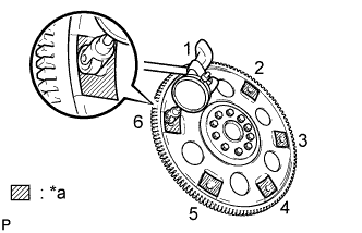
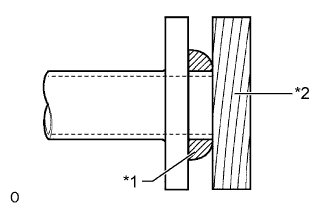
Install the front spacer, drive plate and rear spacer to the crankshaft.
Text in Illustration *1 Front Drive Plate Spacer *2 Drive Plate and Ring Gear *3 Rear Drive Plate Spacer Transmission Side - HINT:
- The front drive plate spacer is reversible.
- As the rear drive plate spacer and drive plate and ring gear are not reversible, be sure to install it so that it is facing in the direction shown in the illustration.
 |
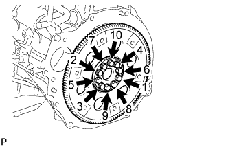
Clean the bolts and bolt holes.
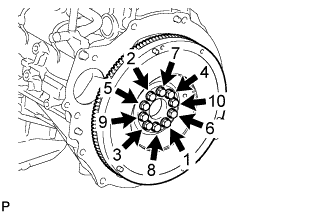
Apply adhesive to 2 or 3 threads at the end of each of the 10 bolts.
- Adhesive:
- Toyota Genuine Adhesive 1324, Three Bond 1324 or equivalent
Install and uniformly tighten the 10 bolts in several steps in the sequence shown in the illustration.
- Torque:
- 74 N*m{755 kgf*cm, 55 ft.*lbf}
- NOTICE:
- Do not start the engine for at least an hour after installing the drive plate.
 |
| 6. INSPECT DRIVE PLATE (for Automatic Transmission) |
Check the drive plate for damage.
Set up a dial indicator and measure the runout of the 6 portions around the torque converter contact surfaces.
- Maximum runout:
- 0.30 mm (0.0118 in.)
If the runout is more than the maximum or the drive plate is damaged, replace the drive plate (HILUX_TGN26 RM000000YMQ01GX_01_0135.html).Text in Illustration *a Measuring point
 |
| 7. INSTALL FLYWHEEL SUB-ASSEMBLY (for Manual Transmission) |
Using SST, hold the crankshaft.
- SST
- 09213-54015(91651-60855)
09330-00021
|
Clean the bolts and bolt holes.
Apply adhesive to 2 or 3 threads at the end of each of the 10 bolts.
- Adhesive:
- Toyota Genuine Adhesive 1324, Three Bond 1324 or equivalent
Install the flywheel with the 10 bolts and uniformly tighten the bolts in several steps in the sequence shown in the illustration.
- Torque:
- 27 N*m{270 kgf*cm, 20 ft.*lbf}
 |
Mark the top of the bolts with paint.
Tighten the 10 bolts 90° in the same sequence.
Check that the paint marks are now at a 90° angle to the top.
| 8. INSTALL CLUTCH DISC ASSEMBLY (for Manual Transmission) |
Insert SST into the clutch disc. Then insert SST (together with the clutch disc) into the flywheel.
- SST
- 09301-00110
- NOTICE:
- Be sure to install the clutch disc so that it is facing in the correct direction.
 |
| 9. INSTALL CLUTCH COVER ASSEMBLY (for Manual Transmission) |
Align the matchmarks on the clutch cover and flywheel.
Text in Illustration *1 Matchmark
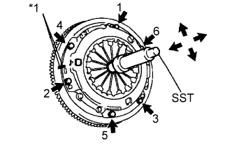 |
Tighten the 6 bolts as described below.
Determine the first bolt to be tightened by choosing the bolt closest to the knock pin.
Uniformly tighten the 6 bolts in diametrically opposite pairs relative to the position of the first bolt. Use the illustration as a reference.
Lightly move SST up and down, and right and left.
- SST
- 09301-00110
Check that the disc is in the center, and then tighten the bolts.
- Torque:
- 19 N*m{195 kgf*cm, 14 ft.*lbf}
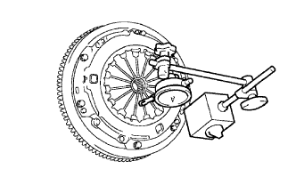
| 10. INSPECT AND ADJUST CLUTCH COVER ASSEMBLY (for Manual Transmission) |
Using a dial indicator with a roller instrument, measure the diaphragm spring tip alignment.
- Maximum misalignment:
- 0.5 mm (0.020 in.)
If the misalignment is more than the maximum, use SST to adjust the diaphragm spring tip alignment.
- SST
- 09333-00013
 |
| 11. INSTALL REAR NO. 1 ENGINE MOUNTING INSULATOR |
- HINT:
- Perform this procedure only when replacement of the rear No. 1 engine mounting insulator is necessary.
Install the 4 bolts and rear No. 1 engine mounting insulator.
- Torque:
- 47 N*m{479 kgf*cm, 35 ft.*lbf}
| 12. INSTALL AUTOMATIC TRANSMISSION ASSEMBLY (for 4WD) |
- A343E:
(HILUX_TGN26 RM0000010NT01VX.html) - A343F:
(HILUX_TGN26 RM0000010NT01QX.html)
| 13. INSTALL MANUAL TRANSMISSION UNIT ASSEMBLY (for Manual Transmission) |
| 14. INSTALL STARTER ASSEMBLY |
Install the starter with the 2 bolts.
- Torque:
- 37 N*m{377 kgf*cm, 27 ft.*lbf}
Install the starter wire to the terminal 30 with the nut.
- Torque:
- 9.8 N*m{100 kgf*cm, 87 in.*lbf}
Connect the terminal cap.
Connect the starter connector.
| 15. INSTALL PROPELLER SHAFT WITH CENTER BEARING ASSEMBLY (for 4WD) |
Completely remove any oil or the like and clean the contact surfaces of the propeller shaft flange and transfer flange.
Align the matchmarks on the propeller shaft flange and transfer flange.
Install the propeller shaft with the 4 nuts and 4 washers.
- Torque:
- 88 N*m{899 kgf*cm, 65 ft.*lbf}
Temporarily install the center support bearing bracket with the 2 plates and 2 bolts. Tighten the bolts as much as possible by hand.
Completely remove any oil or the like and clean the contact surfaces of the propeller shaft flange and differential flange.
Align the matchmarks on the propeller shaft flange and differential flange.
Connect the propeller shaft with the 4 bolts, 4 washers and 4 nuts.
- Torque:
- 88 N*m{899 kgf*cm, 65 ft.*lbf}
Unload the vehicle. The center lines of the center bearing and center bearing housing (refer to the illustration) must be adjusted so that they are within 0 +/-1 mm (0 +/-0.0394 in.) of each other. Measure the difference along the front/rear axis of the vehicle.
Text in Illustration *a Center Bearing Housing Center Line *b Center Bearing Center Line - Distance (A):
- 0 +/-1 mm (0 +/-0.0394 in.)
 |
Tighten the 2 bolts of the center support bearing bracket.
- Torque:
- 36 N*m{369 kgf*cm, 27 ft.*lbf}
| 16. INSTALL PROPELLER SHAFT WITH CENTER BEARING ASSEMBLY (for Pre-Runner) |
Remove SST from the extension housing.
Install the propeller shaft to the extension housing.
Temporarily install the center support bearing bracket with the 2 plates and 2 bolts. Tighten the bolts as much as possible by hand.
Completely remove any oil or the like and clean the contact surfaces of the propeller shaft flange and differential flange.
Align the matchmarks on the propeller shaft flange and differential flange.
Connect the propeller shaft with the 4 bolts, 4 washers and 4 nuts.
- Torque:
- 88 N*m{899 kgf*cm, 65 ft.*lbf}
Unload the vehicle. The center lines of the center bearing and center bearing housing (refer to the illustration) must be adjusted so that they are within 0 +/-1 mm (0 +/-0.0394 in.) of each other. Measure the difference along the front/rear axis of the vehicle.
Text in Illustration *a Center Bearing Housing Center Line *b Center Bearing Center Line - Distance (A):
- 0 +/-1 mm (0 +/-0.0394 in.)
|
Tighten the 2 bolts of the center support bearing bracket.
- Torque:
- 36 N*m{369 kgf*cm, 27 ft.*lbf}
| 17. INSTALL FRONT PROPELLER SHAFT ASSEMBLY (for 4WD) |
Completely remove any oil or the like and clean the contact surfaces of the propeller shaft flange and transfer flange.
Align the matchmarks on the propeller shaft flange and transfer flange.
Install the propeller shaft with the 4 nuts and 4 washers.
- Torque:
- 88 N*m{899 kgf*cm, 65 ft.*lbf}
Completely remove any oil or the like and clean the contact surfaces of the propeller shaft flange and differential flange.
Align the matchmarks on the propeller shaft flange and differential flange.
Connect the propeller shaft with the 4 bolts, 4 nuts and 4 washers.
- Torque:
- 88 N*m{899 kgf*cm, 65 ft.*lbf}
| 18. INSTALL FRONT EXHAUST PIPE ASSEMBLY |
Using a vernier caliper, measure the free length of the compression spring.
- Minimum free length:
- 40 mm (1.57 in.)
 |
Install the front exhaust pipe to the exhaust pipe support.
Using a plastic-faced hammer and wooden block, tap on a new gasket until its surface is flush with the exhaust manifold.
Text in Illustration *1 Gasket *2 Wooden Block - NOTICE:
- Be sure to install the gasket so that it faces the correct direction.
- Do not reuse the gasket.
- Do not damage the gasket.
- When connecting the exhaust pipe, do not push in the gasket with the exhaust pipe.
 |
Connect the front exhaust pipe to the exhaust manifold with the 2 compression springs and 2 bolts. Alternately tighten the bolts in several passes.
- Torque:
- 43 N*m{438 kgf*cm, 32 ft.*lbf}
Install a new gasket and connect the front exhaust pipe to the center exhaust pipe with the 2 bolts and 2 nuts.
- Torque:
- 48 N*m{489 kgf*cm, 35 ft.*lbf}
Connect the heated oxygen sensor connector and attach the wire harness clamp.
Connect the air fuel ratio sensor connector and attach the wire harness clamp.
| 19. INSTALL HOOD ASSEMBLY |
Install the hood with the 4 bolts.
- Torque:
- 13 N*m{133 kgf*cm, 10 ft.*lbf}
Connect the washer nozzle hose.
Adjust the hood (HILUX_TGN26 RM00000138K01ZX.html).
| 20. INSTALL COOLER COMPRESSOR ASSEMBLY (w/ Air Conditioning System) |
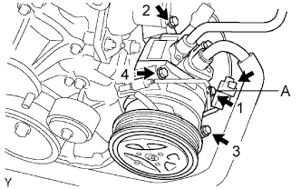 |
Temporarily install the compressor with the bolt labeled A.
Install the compressor completely by tightening the 4 bolts in the order shown in the illustration.
- Torque:
- 25 N*m{250 kgf*cm, 18 ft.*lbf}
- NOTICE:
- In order to prevent misalignment, which causes belt rattle, tightening of the bolts must be performed in the order shown.
Connect the compressor connector.
Install the suction hose with the bolt.
- Torque:
- 5.4 N*m{55 kgf*cm, 48 in.*lbf}
| 21. INSTALL ENGINE OIL LEVEL DIPSTICK GUIDE |
Install a new O-ring and the engine oil level dipstick guide with the bolt.
- Torque:
- 8.0 N*m{82 kgf*cm, 71 in.*lbf}
| 22. INSTALL ENGINE OIL LEVEL DIPSTICK |
| 23. CONNECT VANE PUMP ASSEMBLY |
Connect the vane pump with the 2 bolts.
- Torque:
- 21 N*m{214 kgf*cm, 15 ft.*lbf}
Connect the oil pressure switch connector.
| 24. CONNECT ENGINE WIRE |
Connect the wire clamp to the front engine mounting bracket LH with the bolt.
- Torque:
- 13 N*m{128 kgf*cm, 9 ft.*lbf}
Connect the 2 engine room junction block connectors and wire clamp.
Connect the cable to the engine room junction block with the nut.
- Torque:
- 13 N*m{133 kgf*cm, 10 ft.*lbf}
Install the engine room relay block cover (side).
Install the engine room relay block cover (upper).
Connect the ground wire with the nut.
- Torque:
- 31 N*m{316 kgf*cm, 23 ft.*lbf}
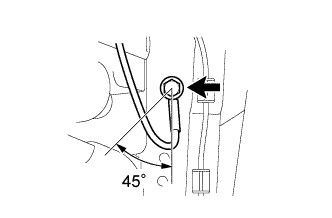
Connect the ground wire to the left side of the frame with the bolt so that it is within the range shown in the illustration.
- Torque:
- 31 N*m{316 kgf*cm, 23 ft.*lbf}
 |
Connect the sensor bracket to the right side of the frame with the bolt.
- Torque:
- 13 N*m{133 kgf*cm, 10 ft.*lbf}
Connect the air fuel ratio sensor connector.
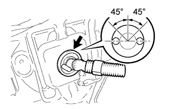
Push the engine wire through the dash panel into the cabin.
- HINT:
- The wire should be within the range shown in the illustration.
 |
Connect the air injection driver connector.
Connect the ECM connectors.
Connect the 4 ECM connectors.
Install the glove compartment door.
| 25. CONNECT FUEL HOSE |
Connect the fuel hose.
| 26. CONNECT NO. 2 FUEL HOSE |
Connect the No. 2 fuel hose.
| 27. CONNECT NO. 1 FUEL HOSE |
Connect the No. 1 fuel hose (HILUX_TGN26 RM000000YL401QX.html).
| 28. CONNECT NO. 4 AIR INJECTION SYSTEM HOSE |
Connect the No. 4 air injection system hose to the air switching valve.
Secure the hose with the clamp.
| 29. CONNECT HOSE |
Connect the vacuum hose (for the brake master cylinder).
Connect the purge line hose.
| 30. CONNECT HEATER WATER HOSE |
Connect the heater water inlet hose and heater water outlet hose to the heater pipe.
| 31. INSTALL RADIATOR ASSEMBLY |
Install the radiator with the 4 bolts.
- Torque:
- 12 N*m{122 kgf*cm, 9 ft.*lbf}
w/ Airbag System:
Attach the 4 clamps to the radiator.
| 32. CONNECT OIL COOLER INLET HOSE (for Automatic Transmission) |
Connect the oil cooler inlet hose to the radiator.
| 33. CONNECT OIL COOLER OUTLET HOSE (for Automatic Transmission) |
Connect the oil cooler outlet hose to the radiator.
| 34. INSTALL FAN PULLEY |
| 35. INSTALL FAN SHROUD |
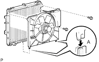 |
Install the fan pulley to the engine water pump.
Place the shroud together with the fluid coupling fan between the radiator and engine.
- NOTICE:
- Be careful not to damage the radiator core.
Install the coupling fan to the water pump with the 4 nuts. Tighten the nuts as much as possible by hand.
Attach the shroud's claws to the radiator as shown in A in the illustration.
Install the fan shroud with the 2 bolts.
- Torque:
- 5.0 N*m{51 kgf*cm, 44 in.*lbf}
Connect the reservoir hose to the radiator tank upper.
Install the fan and generator V belt (HILUX_TGN26 RM000000YMN01PX.html).
Tighten the 4 nuts of the fluid coupling fan.
- Torque:
- 25 N*m{255 kgf*cm, 18 ft.*lbf}
| 36. INSTALL AIR PUMP INLET |
Connect the air pump inlet to the radiator with the bolt.
- Torque:
- 8.5 N*m{87 kgf*cm, 75 in.*lbf}
| 37. INSTALL FAN AND GENERATOR V BELT |
Install the fan and generator V belt to all the pulleys except the V-ribbed belt tensioner pulley.
Text in Illustration *A w/ Air Conditioning System *B w/o Air Conditioning System *1 Generator *2 Idler Pulley *3 Vane Pump *4 Fan Pulley *5 Tensioner Pulley *6 Crankshaft Pulley *7 No. 1 Idler Pulley *8 Cooler Compressor
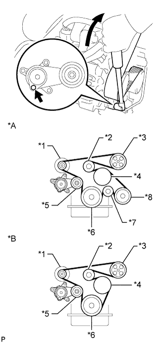 |
Use the hexagon-shaped part indicated by the arrow in the illustration to move the tensioner pulley downward, and then install the fan and generator V belt to the tensioner pulley.
- NOTICE:
- The backside of the fan and generator V belt should face the tensioner pulley.
- Check that the fan and generator V belt is properly installed to each pulley.
| 38. CONNECT RADIATOR HOSE OUTLET |
Connect the radiator hose outlet to the radiator.
| 39. CONNECT RADIATOR HOSE INLET |
Connect the radiator hose inlet to the radiator.
| 40. INSTALL RADIATOR GRILLE |
Attach the 6 claws to install the radiator grille.
Install the 2 screws and 2 clips.
| 41. INSTALL INTAKE AIR CONNECTOR AND AIR CLEANER ASSEMBLY |
Install the air cleaner and intake air connector assembly with the 4 bolts, and tighten the hose clamp.
- Torque:
- for air cleaner:
- 14 N*m{143 kgf*cm, 10 ft.*lbf}
- for intake air connector:
- 8.0 N*m{82 kgf*cm, 71 in.*lbf}
- for hose clamp:
- 5.0 N*m{51 kgf*cm, 44 in.*lbf}
Connect the mass air flow meter connector and attach the wire harness clamps.
Connect the No. 2 PCV hose.
Connect the vacuum hose.
| 42. CONNECT CABLE TO NEGATIVE BATTERY TERMINAL |
- NOTICE:
- When disconnecting the cable, some systems need to be initialized after the cable is reconnected (HILUX_TGN26 RM000004QR3009X.html).
| 43. ADD ENGINE OIL |
Add fresh engine oil.
- Standard Oil Grade:
Oil Grade Oil Viscosity (SAE) API grade SL "Energy-Conserving", SM "Energy-Conserving", SN "Resource-Conserving" or ILSAC multigrade engine oil 5W-30
10W-30
(5W-30 is the best choice for good fuel economy and good starting in cold weather)API grade SL, SM or SN multigrade engine oil 15W-40
20W-50
- Standard Capacity:
Item Capacity Drain and refill without oil filter change 5.3 liters (5.6 US qts, 4.7 Imp. qts) Drain and refill with oil filter change 5.6 liters (5.9 US qts, 4.9 Imp. qts) Dry fill 6.3 liters (6.7 US qts, 5.5 Imp. qts)
Install the oil filler cap.
| 44. ADD ENGINE COOLANT |
Tighten all the plugs and fill the radiator with TOYOTA Super Long Life Coolant (SLLC).
- Torque:
- for Cylinder block drain cock plug:
- 13 N*m{130 kgf*cm, 9 ft.*lbf}
- Standard Capacity:
Item Specified Condition A/T 8.1 liters (8.6 US qts, 7.1 Imp. qts) M/T 7.8 liters (8.2 US qts, 6.9 Imp. qts)
- NOTICE:
- Never use water as a substitute for engine coolant.
- HINT:
- TOYOTA vehicles are filled with TOYOTA SLLC at the factory. In order to avoid damage to the engine cooling system and other technical problems, only use TOYOTA SLLC or similar high quality ethylene glycol based non-silicate, non-amine, non-nitrite, non-borate coolant with long-life hybrid organic acid technology (coolant with long-life hybrid organic acid technology is a combination of low phosphates and organic acids).
- Please contact your TOYOTA dealer for further details.
Fill the radiator reservoir with TOYOTA SLLC to the F line.
Press the inlet and outlet radiator hoses several times by hand, and then check the level of the coolant.
If the coolant level drops below the F line, add TOYOTA SLLC to the F line.
Install the radiator cap.
Bleed air from the cooling system.
Warm up the engine until the thermostat opens.
While the thermostat is open, circulate the coolant for several minutes.Maintain the engine speed at 2500 to 3000 rpm.
Press the inlet and outlet radiator hoses several times by hand to bleed air.
- CAUTION:
- When pressing the radiator hoses:
- Wear protective gloves.
- Be careful as the radiator hoses are hot.
- Keep your hands away from the radiator fan.
Stop the engine and wait until the coolant cools down to ambient temperature.
- CAUTION:
- Do not remove the radiator cap while the engine and radiator are still hot. Pressurized, hot engine coolant and steam may be released and cause serious burns.
Check the coolant level in the radiator reservoir.
If the coolant level is below the L line, add SLLC up to the reservoir F line.
| 45. ADD AUTOMATIC TRANSMISSION FLUID (for Automatic Transmission) |
| 46. INSPECT AUTOMATIC TRANSMISSION FLUID (for Automatic Transmission) |
| 47. ADD MANUAL TRANSMISSION OIL (for Manual Transmission) |
Add manual transmission oil until the oil level is within 5 mm (0.196 in.) from the bottom of the filler plug opening.
Text in Illustration *a 0 to 5 mm (0 to 0.196 in.) - Oil grade:
- GL-4 or GL-5
- Viscosity:
- SAE 75W-90, 80 or 80W-90
- Standard capacity:
- 2.6 liters (2.7 US qts, 2.3 Imp. qts)
 |
Install a new gasket and the filler plug.
- Torque:
- 37 N*m{377 kgf*cm, 27 ft.*lbf}
| 48. INSPECT FOR FUEL LEAK (for Fuel Main Tank) |
Make sure that there are no fuel leaks after performing maintenance on the fuel system.
Connect the intelligent tester to the DLC3.
Turn the ignition switch to ON and turn the intelligent tester on.
- NOTICE:
- Do not start the engine.
Enter the following menus: Powertrain / Engine and ECT / Active Test / Control the Fuel Pump / Speed.
Check that there are no leaks from the fuel system.
If there are fuel leaks, repair or replace parts as necessary.Turn the ignition switch off.
Disconnect the intelligent tester from the DLC3.
| 49. INSPECT FOR FUEL LEAK (for Fuel Sub Tank) |
Start the engine.
- NOTICE:
- Perform the inspection while the engine is cold.
- The fuel pump operates only for a calculated time when the coolant temperature is 20°C (68°F) or less and learned ethanol concentration is 85% or more.
Check for fuel leaks.
Check that there are no fuel leaks from the fuel system after doing any maintenance or repairs. If there is a fuel leak, repair or replace parts as necessary.
| 50. INSPECT FOR OIL LEAK |
Start the engine, and check that there are no oil leaks after performing maintenance.
| 51. INSPECT FOR COOLANT LEAK |
- CAUTION:
- Do not remove the radiator cap while the engine and radiator are still hot. Pressurized, hot engine coolant and steam may be released and cause serious burns.
Fill the radiator with coolant and attach a radiator cap tester.
Warm up the engine.
Using a radiator cap tester, increase the pressure inside the radiator to 118 kPa (1.2 kgf/cm2, 17 psi), and check that the pressure does not drop.
If the pressure drops, check the hoses, radiator and water pump for leaks. If no external leaks are found, check the cylinder block and cylinder head.
| 52. INSPECT FOR EXHAUST GAS LEAK |
| 53. INSTALL NO. 2 ENGINE UNDER COVER |
- Torque:
- 28 N*m{286 kgf*cm, 21 ft.*lbf}
| 54. INSTALL NO. 1 ENGINE UNDER COVER |
- Torque:
- 28 N*m{286 kgf*cm, 21 ft.*lbf}
| 55. INSPECT IGNITION TIMING |
Warm up and stop the engine.
When using the intelligent tester:
Connect the intelligent tester to the DLC3.
- NOTICE:
- Switch off all the accessories and the A/C before connecting the intelligent tester.
Start the engine and idle it.
Turn the intelligent tester main switch on.
Enter the following menus: Powertrain / Engine and ECT / Data List / IGN Advance.
- Standard ignition timing:
- 0 to 20° BTDC @ idle
- NOTICE:
- When checking the ignition timing, the transmission should be in neutral or park.
- HINT:
- Refer to the intelligent tester operator's manual for further details.
Check that the ignition timing advances immediately when the engine speed is increased.
Enter the following menus: Powertrain / Engine and ECT / Active Test / Connect the TC and TE1.
Monitor IGN Advance.
Perform the Active Test.
- Standard ignition timing:
- 3 to 7° BTDC @ idle
- NOTICE:
- When checking the ignition timing, the transmission should be in neutral or park.
- HINT:
- Refer to the intelligent tester operator's manual for further details.
When not using the intelligent tester:
Using SST, connect a tachometer probe to terminal 9 (TAC) of the DLC3.
- SST
- 09843-18030
Text in Illustration *a Front view of DLC3 - NOTICE:
- Confirm the terminal number before connecting the probe. Connecting the wrong terminals can damage the engine.
- Turn off all electrical systems before connecting the probe.
Connect the tester probe of a timing light to the wire of the ignition coil connector for the No. 1 cylinder.
Start the engine and idle it.
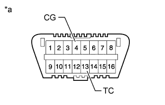
Using SST, connect terminals 13 (TC) and 4 (CG) of the DLC3.
- SST
- 09843-18040
Text in Illustration *a Front view of DLC3 - NOTICE:
- When checking the ignition timing, the transmission should be in neutral.
- HINT:
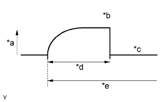
- After connecting terminals TC and CG, the engine speed changes to between approximately 1000 and 1500 rpm for 5 seconds, and then returns to idle as the ECM checks that the ISC (Idle Speed Control) system operates properly.
- Inspect the ignition timing after the engine speed returns to idle.
Text in Illustration *a Engine Speed *b Approx. 1000 to 1500 rpm *c Idle Speed *d 5 sec. *e Connect Terminals TC and CG Using the timing light, measure the ignition timing.
- Standard ignition timing:
- 3 to 7° BTDC @ idle
- NOTICE:
- Turn all the electrical systems and the A/C off.
- When checking the ignition timing, the transmission should be in neutral or park.
Remove SST from the DLC3.
Check the ignition timing.
- Standard ignition timing:
- 0 to 20° BTDC @ idle
Confirm that the ignition timing advances immediately when the engine speed is increased.
Turn the ignition switch off.
Disconnect the timing light from the engine.

| 56. INSPECT ENGINE IDLE SPEED |
Warm up and stop the engine.
When using the intelligent tester:
Connect the intelligent tester to the DLC3.
- NOTICE:
- Switch off all accessories and the air conditioning before connecting the intelligent tester.
Start the engine and idle it.
Turn the intelligent tester on.
Enter the following menus: Powertrain / Engine and ECT / Data List / Engine SPD.
- Standard idle speed:
- 600 to 700 rpm
- NOTICE:
- When checking the idle speed, the transmission should be in neutral.
- HINT:
- Refer to the intelligent tester operator's manual for further details.
Turn the ignition switch off.
Disconnect the intelligent tester from the DLC3.
When not using the intelligent tester:
Using SST, connect a tachometer tester probe to terminal 9 (TAC) of the DLC3.
- SST
- 09843-18030
Text in Illustration *a Front view of DLC3 Start the engine and idle it.
Check the idle speed.
- Standard idle speed:
- 600 to 700 rpm
| 57. CHECK CO/HC |
Start and warm up the engine.
Run the engine at 2500 rpm for approximately 180 seconds, and then idle the engine.
Insert a CO/HC meter testing probe at least 40 cm (1.31 ft.) into the tailpipe.
Check the CO/HC concentration at idle.
- Standard idle CO concentration:
- 0 to 0.5%
- Standard idle HC concentration:
- Refer to applicable local regulation
If the CO/HC concentration is not as specified, perform troubleshooting in the order given below.
Check the air fuel ratio sensor (HILUX_TGN26 RM000001421010X.html) and heated oxygen sensor operation (HILUX_TGN26 RM00000159K00JX.html).
See the table below for possible causes, and then inspect and repair the applicable causes if necessary.
CO HC Problems Causes Normal High Rough idle - Faulty ignition:
- Incorrect timing
- Fouled, shorted or improperly gapped plugs
- Incorrect valve clearance
- Leaks in intake and exhaust valves
- Leaks in cylinders
Low High Rough idle
(Fluctuating HC reading)- Vacuum leaks:
- PCV hoses
- Intake manifold
- Throttle body
- Brake booster line
- Lean mixture causing misfire
High High Rough idle
(Black smoke from exhaust)- Restricted air cleaner filter element
- Plugged PCV valve
- Faulty SFI system:
- Faulty pressure regulator
- Defective engine coolant temperature sensor
- Defective mass air flow meter
- Faulty ECM
- Faulty injectors
- Faulty throttle position sensor
- Faulty ignition:
| 58. CHECK FUNCTION OF THROTTLE BODY |
Check the throttle control motor operating sound.
Turn the ignition switch to ON.
When depressing the accelerator pedal, check the operating sound of the running motor. Make sure that no friction noises are emitted from the motor. If friction noise exists, replace the throttle body.
Check the throttle position sensor.
Connect the intelligent tester to the DLC3.
Turn the ignition switch to ON.
Turn the intelligent tester on.
Enter the following menus: Powertrain / Engine and ECT / Data List / All Data / Throttle Sensor Position.
- Standard throttle valve opening percentage:
- 60% or more
- NOTICE:
- When checking the standard throttle valve opening percentage, make sure the transmission is in neutral.