DISCHARGE FUEL SYSTEM PRESSURE
PRECAUTION
DISCONNECT CABLE FROM NEGATIVE BATTERY TERMINAL
REMOVE FUEL TANK CAP ASSEMBLY
REMOVE NO. 1 FUEL TANK PROTECTOR
REMOVE NO. 3 FUEL TUBE CLAMP
DISCONNECT FUEL TANK MAIN TUBE SUB-ASSEMBLY AND FUEL TANK RETURN TUBE
DISCONNECT FUEL TANK TO FILLER PIPE HOSE
DISCONNECT FUEL TANK BREATHER HOSE
REMOVE FUEL TANK INLET PIPE SUB-ASSEMBLY
REMOVE FUEL TANK ASSEMBLY
REMOVE NO. 1 FUEL TANK HEAT INSULATOR
REMOVE NO. 1 FUEL TANK CUSHION
REMOVE VENT LINE TUBE
REMOVE FUEL PUMP GAUGE RETAINER
REMOVE FUEL SUCTION WITH PUMP AND GAUGE TUBE ASSEMBLY
REMOVE NO. 2 FUEL TANK PROTECTOR
REMOVE FUEL TANK BREATHER HOSE
REMOVE FUEL TANK TO FILLER PIPE HOSE
- NOTICE:
- These procedures should be performed with the fuel tank less than 1/4 full.
| 1. DISCHARGE FUEL SYSTEM PRESSURE |
(HILUX_TGN26 RM000000YL401AX.html)
- NOTICE:
- After turning the ignition switch off, waiting time may be required before disconnecting the cable from the battery terminal. Therefore, make sure to read the disconnecting the cable from the battery terminal notice before proceeding with work (HILUX_TGN26 RM000004QR1003X.html).
| 3. DISCONNECT CABLE FROM NEGATIVE BATTERY TERMINAL |
- NOTICE:
- When disconnecting the cable, some systems need to be initialized after the cable is reconnected (HILUX_TGN26 RM000004QR3003X.html).
| 4. REMOVE FUEL TANK CAP ASSEMBLY |
| 5. REMOVE NO. 1 FUEL TANK PROTECTOR |
Remove the 4 nuts and No. 1 fuel tank protector.
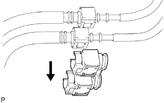
| 6. REMOVE NO. 3 FUEL TUBE CLAMP |
Remove the tube clamp from the fuel tube.
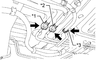
| 7. DISCONNECT FUEL TANK MAIN TUBE SUB-ASSEMBLY AND FUEL TANK RETURN TUBE |
Disconnect the fuel tank main tube (HILUX_TGN26 RM000000YL401AX.html).
Text in Illustration*1
| Fuel Main Tube
|
*2
| Fuel Return Tube
|
*3
| Vent Line Hose
|
Disconnect the fuel tank return tube (HILUX_TGN26 RM000000YL401AX.html).
Disconnect the vent line hose.
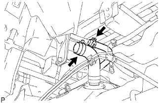
| 8. DISCONNECT FUEL TANK TO FILLER PIPE HOSE |
Disconnect the fuel tank to filler pipe hose from the fuel tank inlet pipe.
| 9. DISCONNECT FUEL TANK BREATHER HOSE |
Disconnect the fuel tank breather hose from the fuel tank inlet pipe.
| 10. REMOVE FUEL TANK INLET PIPE SUB-ASSEMBLY |
Remove the bolt and fuel tank inlet pipe.
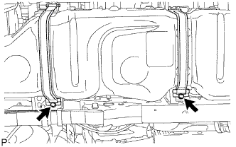
| 11. REMOVE FUEL TANK ASSEMBLY |
Place an engine lifter under the fuel tank.
Remove the 2 bolts, 2 clips, 2 pins and 2 fuel tank bands.
Slightly lower the engine lifter.
- NOTICE:
- Be careful not to cut the wiring.
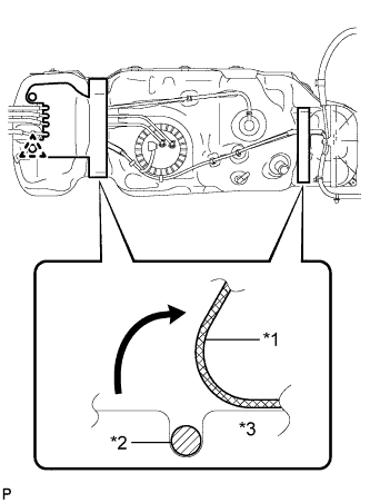
Remove the clip. Then fold back approximately half of each cushion rubber so that the wire harness can be removed in the step below.
Text in Illustration*1
| Fuel Tank Cushion
|
*2
| Wire Harness
|
*3
| Fuel Tank
|
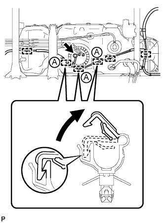
Detach the wire harness from the 6 clamps shown in the illustration.
- HINT:
- Detach the claws of the clamps labeled A in the illustration to detach the wire harness.
Disconnect the fuel pump and sender gauge connector.
| 12. REMOVE NO. 1 FUEL TANK HEAT INSULATOR |
Using needle-nose pliers, remove the 4 clips and nut as shown in the illustration, and then remove the No. 1 fuel tank heat insulator.
Text in Illustration*1
| Needle-nose Pliers
|

| Clip
|

| Nut
|
| 13. REMOVE NO. 1 FUEL TANK CUSHION |
Remove the clip and 2 fuel tank cushions from the fuel tank.
| 14. REMOVE VENT LINE TUBE |
Disconnect the vent line hose and remove the vent line tube.
| 15. REMOVE FUEL PUMP GAUGE RETAINER |
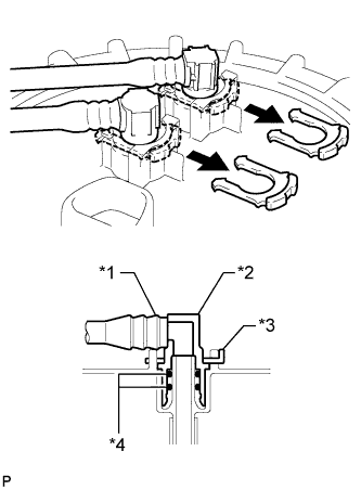
Remove the 2 tube joint clips and pull out the 2 fuel tank tubes.
Text in Illustration*1
| Fuel Tube
|
*2
| Fuel Tube Joint
|
*3
| Tube Joint Clip
|
*4
| O-Ring
|
- NOTICE:
- Remove any dirt and foreign matter on the fuel tube joint before performing this work.
- Do not allow any scratches or foreign matter on the parts when disconnecting them, as the fuel tube joint contains the O-rings that seal the plug.
- Perform this work by hand. Do not use any tools.
- Do not forcibly bend, twist or turn the nylon tube.
- Protect the disconnected part by covering it with a plastic bag and tape after disconnecting the fuel tubes.
Remove the fuel tank return tube and fuel tank main tube from the fuel tank.
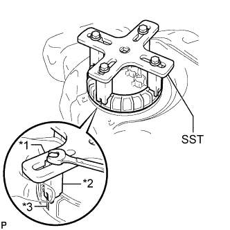
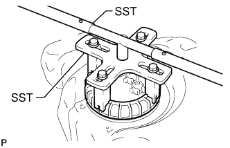
Temporarily install SST (plate and 4 claws) to the fuel pump gauge retainer.
- SST
- 09808-14030
Text in Illustration*1
| SST (Plate)
|
*2
| SST (Claw)
|
*3
| Rib
|
- HINT:
- Be sure to use 4 SST (claws) as shown in the illustration.
- Engage SST (claws) securely with the fuel pump gauge retainer ribs to secure SST.
While pressing SST (claws) against the fuel pump gauge retainer ribs securely, install the 4 bolts.
- HINT:
- Install SST while pressing SST (claws) against the fuel pump gauge retainer (towards the center of SST).
Install SST (handle).
Lightly press down on SST to prevent it from separating from the fuel pump gauge retainer. While pressing SST, rotate the handle slowly to loosen the fuel pump gauge retainer.
- SST
- 09808-14030
- NOTICE:
- When the retainer is loosened, be careful as the fuel pump will spring upward from the force of the spring.
- Do not use any tools other than specified in this operation. Damage to the fuel pump gauge retainer or the fuel tank may result.
- Do not press down on SST excessively as this may make the fuel pump gauge retainer hard to rotate, and may damage components.
- Make sure to rotate SST (handle) horizontally. If SST (handle) is rotated at an angle, SST may come off.
- Do not spin SST too fast or use an impact wrench as this may result in damage to components.
- If SST comes off of the fuel pump gauge retainer, loosen SST (bolts) and reinstall SST.
- HINT:
- The tips of SST (claws) can be fitted onto the ribs of the fuel pump gauge retainer.
Remove the fuel pump gauge retainer.
| 16. REMOVE FUEL SUCTION WITH PUMP AND GAUGE TUBE ASSEMBLY |
Remove the fuel suction with pump and gauge tube from the fuel tank.
- NOTICE:
- Be careful not to bend the arm of the fuel sender gauge.
Remove the gasket from the fuel tank.
| 17. REMOVE NO. 2 FUEL TANK PROTECTOR |
Detach the 2 claws and remove the protector.
| 18. REMOVE FUEL TANK BREATHER HOSE |
Remove the fuel tank breather hose from the fuel tank.
| 19. REMOVE FUEL TANK TO FILLER PIPE HOSE |
Remove the fuel tank to filler pipe hose from the fuel tank.