Dtc C1241/41 Low Battery Positive Voltage Or Abnormally High Battery Positive Voltage
Brake. Hilux. Tgn26, 36 Kun25, 26, 35, 36 Ggn25
DESCRIPTION
WIRING DIAGRAM
INSPECTION PROCEDURE
INSPECT BATTERY
CHECK TERMINAL VOLTAGE (IG1 TERMINAL)
CHECK HARNESS AND CONNECTOR (GROUND CIRCUIT)
RECONFIRM DTC
DTC C1241/41 Low Battery Positive Voltage or Abnormally High Battery Positive Voltage |
DESCRIPTION
This DTC is stored when the IG1 terminal voltage deviates from the DTC detection condition due to a malfunction in the power supply or charging circuit, such as the battery or generator circuit, etc.DTC Code
| DTC Detection Condition
| Trouble Area
|
C1241/41
| Either condition is met:
- Both conditions continue for at least 10 seconds.
- Vehicle speed is more than 3 km/h (2 mph).
- The IG1 terminal voltage is below 9.5 V.
- All conditions continue for at least 0.2 seconds
- Solenoid relay remains on.
- Relay contact is open.
- The IG1 terminal voltage is below 9.5 V.
| - ECU-IG&GAUGE fuse
- Battery
- Charging system
- Power source circuit
- Internal power supply circuit of skid control ECU (Brake actuator assembly)
|
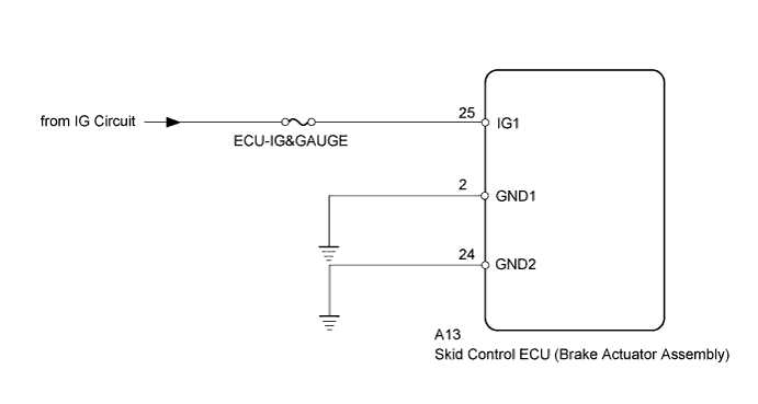
WIRING DIAGRAM
INSPECTION PROCEDURE
- NOTICE:
- Inspect the fuses for circuits related to this system before performing the following inspection procedure.
- Before disconnecting the connector, make sure that there are no problems with the connection.
- After disconnecting the connector, make sure that the connector case and terminals are not deformed or corroded.
Check the battery voltage.
- Standard voltage:
- 11 to 14 V
ResultResult
| Proceed to
|
OK
| A
|
NG (for 1KD-FTV)
| B
|
NG (for 2KD-FTV)
| C
|
NG (for 2TR-FE)
| D
|
NG (for 2TR-FBE)
| E
|
| 2.CHECK TERMINAL VOLTAGE (IG1 TERMINAL) |
Turn the ignition switch off.
Disconnect the skid control ECU (brake actuator assembly) connector.
Measure the voltage according to the value(s) in the table below.
- Standard Voltage:
Tester Connection
| Switch Condition
| Specified Condition
|
A13-25 (IG1) - Body ground
| Ignition switch ON
| 11 to 14 V
|
Text in Illustration*a
| Front view of wire harness connector
(to Skid Control ECU [Brake Actuator Assembly])
|
| | REPAIR OR REPLACE HARNESS OR CONNECTOR |
|
|
| 3.CHECK HARNESS AND CONNECTOR (GROUND CIRCUIT) |
Turn the ignition switch off.
Disconnect the skid control ECU (brake actuator assembly) connector.
Measure the resistance according to the value(s) in the table below.
- Standard Resistance:
Tester Connection
| Condition
| Specified Condition
|
A13-2 (GND1) - Body ground
| Always
| Below 1 Ω
|
A13-24 (GND2) - Body ground
| Always
| Below 1 Ω
|
Text in Illustration*a
| Front view of wire harness connector
(to Skid Control ECU [Brake Actuator Assembly])
|
| | REPAIR OR REPLACE HARNESS OR CONNECTOR |
|
|
Clear the DTC (HILUX_TGN26 RM000000XHV0CFX.html).
Turn the ignition switch off.
Start the engine.
Drive the vehicle at a speed of 20 km/h (12 mph) or more for 30 seconds or more.
Check if the same DTC is output (HILUX_TGN26 RM000000XHV0CFX.html).
ResultResult
| Proceed to
|
DTC not output
| A
|
DTC output
| B
|
- HINT:
- If troubleshooting has been carried out according to the problem symptoms table, refer back to the table and proceed to the next step (HILUX_TGN26 RM000000XHN0CQX.html).