Dtc P0340 Camshaft Position Sensor Circuit Malfunction
DESCRIPTION
MONITOR DESCRIPTION
MONITOR STRATEGY
CONFIRMATION DRIVING PATTERN
WIRING DIAGRAM
INSPECTION PROCEDURE
INSPECT CAMSHAFT POSITION SENSOR (RESISTANCE)
CHECK HARNESS AND CONNECTOR (CAMSHAFT POSITION SENSOR - ECM)
CHECK SENSOR INSTALLATION (CAMSHAFT POSITION SENSOR)
INSPECT CAMSHAFT TIMING GEAR ASSEMBLY (TEETH)
REPLACE CAMSHAFT POSITION SENSOR
CHECK WHETHER DTC OUTPUT RECURS
DTC P0340 Camshaft Position Sensor Circuit Malfunction |
DTC P0341 Camshaft Position Sensor "A" Circuit Range / Performance (Bank 1 or Single Sensor) |
DESCRIPTION
The camshaft position sensor consists of a magnet and an iron core which is wrapped with copper wire, and is installed on the cylinder head. When the camshaft rotates, each of the 3 teeth on the camshaft pass through the camshaft position sensor. This activates the internal magnet in the sensor, generating a voltage in the copper wire. The camshaft rotation is synchronized with the crankshaft rotation. When the crankshaft turns twice, the voltage is generated 3 times in the camshaft position sensor. The generated voltage in the sensor acts as a signal, allowing the ECM to locate the camshaft position. This signal is then used to control ignition timing, fuel injection timing, and the VVT system.DTC No.
| DTC Detection Condition
| Trouble Area
|
P0340
| When one of the following conditions is met:
- No camshaft position sensor signal is sent to the ECM while cranking (1 trip detection logic).
- The camshaft position sensor signal is missing despite the crankshaft position sensor input being normal at an engine speed of 600 rpm or more (1 trip detection logic).
| - Open or short in camshaft position sensor circuit
- Camshaft position sensor
- Camshaft timing gear assembly
- Timing chain for intake camshaft jumped tooth
- ECM
|
P0341
| While the crankshaft rotates twice, the camshaft position sensor signal is input to the ECM 12 times or more (1 trip detection logic).
| - Open or short in camshaft position sensor circuit
- Camshaft position sensor
- Camshaft timing gear assembly
- Timing chain for intake camshaft jumped tooth
- ECM
|
- HINT:
- DTC P0340 indicates a malfunction related to the camshaft position sensor (+) circuit (the wire harness between the ECM and camshaft position sensor, and the camshaft position sensor itself).
- DTC P0341 indicates a malfunction related to the camshaft position sensor (-) circuit (the wire harness between the ECM and camshaft position sensor, and the camshaft position sensor itself).
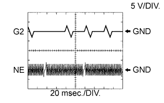
- Reference: Inspection using an oscilloscope.
- HINT:
- G2 stands for the camshaft position sensor signal and NE stands for the crankshaft position sensor signal.
- Grounding failure of the shielded wire may cause noise in the waveforms.
Tester Connection
| Tool Setting
| Condition
| Specified Condition
|
C75-27 (NE+) - C75-34 (NE-)
| 5 V/DIV, 20 ms/DIV
| Idling
| The correct waveform is as shown
|
C75-26 (G2) - C75-34 (NE-)
| 5 V/DIV, 20 ms/DIV
| Idling
| The correct waveform is as shown
|
MONITOR DESCRIPTION
- P0340:
If no signal is transmitted by the camshaft position sensor despite the engine running, or the rotations of the camshaft and crankshaft are not synchronized, the ECM interprets this as a malfunction of the circuit.
- P0341:
If the G signal is input 12 or more times in the time it takes for the signal indicating top dead center to be input 3 times, the ECM interprets this as a malfunction of the circuit.
MONITOR STRATEGY
Required Sensors/Components (Main)
| Camshaft position sensor
|
Required Sensors/Components (Related)
| Crankshaft position sensor
|
Frequency of Operation
| Continuous
|
CONFIRMATION DRIVING PATTERN
- Start the engine and run it at idle for 10 seconds or more.
WIRING DIAGRAM
INSPECTION PROCEDURE
- HINT:
- Read freeze frame data using the intelligent tester. Freeze frame data records the engine conditions when malfunctions are detected. When troubleshooting, freeze frame data can help determine if the vehicle was moving or stationary, if the engine was warmed up or not, if the air-fuel ratio was lean or rich, and other data from the time the malfunction occurred.
| 1.INSPECT CAMSHAFT POSITION SENSOR (RESISTANCE) |
Inspect the camshaft position sensor (HILUX_TGN26 RM000000VX501JX.html).
| 2.CHECK HARNESS AND CONNECTOR (CAMSHAFT POSITION SENSOR - ECM) |
Disconnect the camshaft position sensor connector.
Disconnect the ECM connector.
Measure the resistance according to the value(s) in the table below.
- Standard Resistance:
Tester Connection
| Condition
| Specified Condition
|
C68-1 - C75-26 (G2)
| Always
| Below 1 Ω
|
C68-2 - C75-34 (NE-)
| Always
| Below 1 Ω
|
C68-1 or C75-26 (G2) - Body ground
| Always
| 10 kΩ or higher
|
C68-2 or C75-34 (NE-) - Body ground
| Always
| 10 kΩ or higher
|
| | REPAIR OR REPLACE HARNESS OR CONNECTOR |
|
|
| 3.CHECK SENSOR INSTALLATION (CAMSHAFT POSITION SENSOR) |
Check the camshaft position sensor.
- OK:
- Sensor is installed correctly.
| 4.INSPECT CAMSHAFT TIMING GEAR ASSEMBLY (TEETH) |
Check the teeth of the camshaft timing gear assembly.
- OK:
- Teeth do not have any cracks or deformation.
| 5.REPLACE CAMSHAFT POSITION SENSOR |
Replace the camshaft position sensor (HILUX_TGN26 RM000000VX701JX.html).
| 6.CHECK WHETHER DTC OUTPUT RECURS |
Connect the intelligent tester to the DLC3.
Turn the ignition switch to ON.
Turn the intelligent tester on.
Clear the DTCs (HILUX_TGN26 RM000000PDK0XSX.html).
Start the engine and idle it for 10 seconds or more.
Enter the following menus: Powertrain / Engine and ECT / DTC / Pending.
Read the DTCs.
ResultResult
| Proceed to
|
No DTC is output
| A
|
P0340 or P0341 is output
| B
|
- HINT:
- If the engine does not start, replace the ECM.