Dtc P0724 Brake Switch B Circuit High
DESCRIPTION
MONITOR DESCRIPTION
MONITOR STRATEGY
CONFIRMATION DRIVING PATTERN
WIRING DIAGRAM
INSPECTION PROCEDURE
CHECK STOP LIGHT SWITCH ASSEMBLY INSTALLATION
INSPECT STOP LIGHT SWITCH ASSEMBLY
CHECK HARNESS AND CONNECTOR (ECM - BATTERY)
DTC P0724 Brake Switch "B" Circuit High |
DESCRIPTION
The stop light switch is part of a duplex system that transmits 2 signals: STP and ST1-. These 2 signals are used by the ECM to monitor whether or not the brake system is working properly. This DTC indicates that the stop light switch remains on. When the stop light switch remains on during GO and STOP driving, the ECM interprets this as a fault in the stop light switch. Then the MIL illuminates and the ECM stores the DTC.DTC No.
| DTC Detection Condition
| Trouble Area
|
P0724
| Stop light switch remains on even when the vehicle is driven in a GO (30 km/h (18.63 mph) or more) and STOP (less than 3 km/h (1.86 mph)) pattern 5 times (2 trip detection logic).
| - Short in stop light switch signal circuit
- Stop light switch assembly
- ECM
|
MONITOR DESCRIPTION
This DTC indicates that the stop light switch remains on. When the stop light switch remains on during GO and STOP driving, the ECM interprets this as a fault in the stop light switch. Then the MIL illuminates and the ECM stores the DTC. The vehicle must GO (30 km/h (18.63 mph) or more) and STOP (less than 3 km/h (1.86 mph)) 5 times for 2 driving cycles in order for the DTC to be stored.
MONITOR STRATEGY
Required sensors/Components
| Stop light switch assembly, Vehicle speed sensor
|
Frequency of operation
| Continuous
|
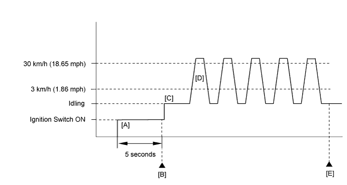
CONFIRMATION DRIVING PATTERN
- Connect the intelligent tester to the DLC3.
- Turn the ignition switch to ON and turn the intelligent tester on.
- Clear the DTCs (even if no DTCs are stored, perform the clear DTC operation).
- Turn the ignition switch off and wait for at least 30 seconds.
- Turn the ignition switch to ON and turn the intelligent tester on [A].
- Wait 5 seconds.
- Enter the following menus: Powertrain / Engine and ECT / DTC [B].
- Read the pending DTCs.
- HINT:
- If a pending DTC is output, the system is malfunctioning.
- If a pending DTC is not output, perform the following procedure.
- Enter the following menus: Powertrain / Engine and ECT / Utility / All Readiness.
- Input the DTC: P0724.
- Check the DTC judgment result.
Intelligent Tester Display
| Description
|
NORMAL
| - DTC judgment completed
- System normal
|
ABNORMAL
| - DTC judgment completed
- System abnormal
|
INCOMPLETE
| - DTC judgment not completed
- Perform driving pattern after confirming DTC enabling conditions
|
N/A
| - Unable to perform DTC judgment
- Number of DTCs which do not fulfill DTC preconditions has reached ECU memory limit
|
- HINT:
- If the judgment result shows NORMAL, the system is normal.
- If the judgment result shows ABNORMAL, the system has a malfunction.
- If the judgment result shows INCOMPLETE or N/A, perform steps [C] through [E].
- Start the engine [C].
- Accelerate the vehicle to 30 km/h (19 mph) or more, and then depress the brake pedal and decelerate the vehicle to 3 km/h (1.8 mph) or less [D]. Repeat step [D] 5 times.
- CAUTION:
- When performing the confirmation driving pattern, obey all speed limits and traffic laws.
- Check the DTC judgment result [E].
WIRING DIAGRAM
Refer to DTC P0504 (HILUX_TGN26 RM000000XCT0QUX_02.html).
INSPECTION PROCEDURE
- HINT:
- Using the intelligent tester, the Data List item "Stop Light Switch" can be read.
Item
| Measurement Item/
Range
| Normal Condition
| Diagnostic Note
|
Stop Light Switch
| Stop light switch status/
ON or OFF
| - Brake pedal depressed: ON
- Brake pedal released: OFF
| -
|
| 1.CHECK STOP LIGHT SWITCH ASSEMBLY INSTALLATION |
Check the stop light switch assembly installation.
- OK:
- Stop light switch assembly is installed correctly.
| 2.INSPECT STOP LIGHT SWITCH ASSEMBLY |
Inspect the stop light switch assembly (HILUX_TGN26 RM0000018VE00SX_01_0001.html).
| 3.CHECK HARNESS AND CONNECTOR (ECM - BATTERY) |
Disconnect the ECM connector.
Measure the voltage according to the value(s) in the table below.
- Standard Voltage:
Tester Connection
| Condition
| Specified Condition
|
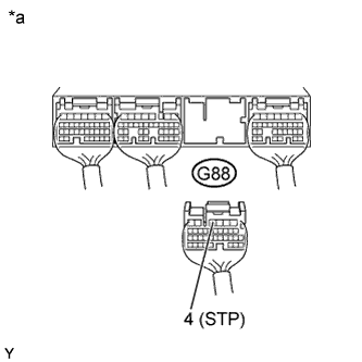
G88-4 (STP) - Body ground
| Brake pedal is depressed
| 11 to 14 V
|
Brake pedal is released
| Below 1 V
|
Text in Illustration*a
| Rear view of wire harness connector
(to ECM)
|
| | REPAIR OR REPLACE HARNESS OR CONNECTOR |
|
|