DESCRIPTION
WIRING DIAGRAM
INSPECTION PROCEDURE
CHECK ECM TERMINAL VOLTAGE (BATT)
INSPECT BATTERY
CHECK BATTERY TERMINAL
CHECK WHETHER DTC OUTPUT RECURS (DTC P0560)
REPLACE ECM
REPAIR OR REPLACE HARNESS OR CONNECTOR
RECHARGE OR REPLACE BATTERY
REPAIR OR REPLACE BATTERY TERMINAL
CONFIRM WHETHER MALFUNCTION HAS BEEN SUCCESSFULLY REPAIRED
DESCRIPTION
The battery supplies electricity to the ECM even when the ignition switch is off. This power allows the ECM to store data such as DTC history, freeze frame data and fuel trim values. If the battery voltage falls below a minimum level, the ECM memory is cleared and the ECM determines that there is a malfunction in the power supply circuit. When the engine is next started, the ECM illuminates the MIL and stores the DTC.P0560DTC Detection Drive Pattern
| DTC Detection Condition
| Trouble Area
|
Ignition switch to ON for 3 seconds
| The voltage at terminal BATT drops excessively for 3 seconds and part of the stored values in the ECM are initialized (1 trip detection logic).
| - Open in backup power source circuit (to BATT terminal)
- Battery
- Battery terminals
- EFI fuse
- ECM
|
Related Data ListDTC No.
| Data List
|
P0560
| Battery Voltage*
|
*: This is not the voltage of the BATT, it is the power supply voltage for the ECM.- HINT:
- If DTC P0560 is stored, the ECM does not store other DTCs or the data stored in the ECM is partly cleared.
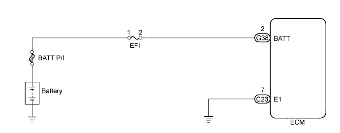
WIRING DIAGRAM
INSPECTION PROCEDURE
- NOTICE:
- Inspect the fuses of circuits related to this system before performing the following inspection procedure.
- After replacing the ECM, the new ECM needs registration (HILUX_TGN26 RM0000012XK071X.html) and initialization (HILUX_TGN26 RM000000TIN04FX.html).
- HINT:
- Read freeze frame data using the intelligent tester. Freeze frame data records the engine condition when malfunctions are detected. When troubleshooting, freeze frame data can help determine if the vehicle was moving or stationary, if the engine was warmed up or not, and other data from the time the malfunction occurred.
- When the ignition switch to ON, even though +B voltage is present, when the voltage at terminal BATT (power supply for maintaining memorized values in the ECM) drops excessively, this DTC is stored.
| 1.CHECK ECM TERMINAL VOLTAGE (BATT) |
Measure the voltage according to the value(s) in the table below.
- Standard Voltage:
Tester Connection
| Condition
| Specified Condition
|
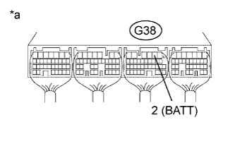
G38-2 (BATT) - Body ground
| Always
| 11 to 14 V
|
Text in Illustration*a
| Component with harness connected
(ECM)
|
Check that the battery is not depleted.
- OK:
- Battery is not depleted.
Check that the battery terminals are not loose or corroded.
- OK:
- Battery terminals are not loose or corroded.
| 4.CHECK WHETHER DTC OUTPUT RECURS (DTC P0560) |
Connect the intelligent tester to the DLC3.
Turn the ignition switch to ON and turn the tester on.
Clear the DTCs (HILUX_TGN26 RM000000PDK120X.html).
Turn the ignition switch off.
Turn the ignition switch to ON for 3 seconds.
Enter the following menus: Powertrain / Engine and ECT / DTC.
Read the DTCs.
ResultResult
| Proceed to
|
P0560 is output
| A
|
No DTC is output
| B
|
Replace the ECM (HILUX_TGN26 RM0000013Z001HX.html).
| 6.REPAIR OR REPLACE HARNESS OR CONNECTOR |
Repair or replace the harness or connector.
| 7.RECHARGE OR REPLACE BATTERY |
Recharge or replace the battery.
| 8.REPAIR OR REPLACE BATTERY TERMINAL |
Repair or replace the battery terminal.
| 9.CONFIRM WHETHER MALFUNCTION HAS BEEN SUCCESSFULLY REPAIRED |
Connect the intelligent tester to the DLC3.
Clear the DTCs (HILUX_TGN26 RM000000PDK120X.html).
Turn the ignition switch off for 30 seconds or more.
Turn the ignition switch to ON for 3 seconds.
Enter the following menus: Powertrain / Engine and ECT / DTC.
Confirm that the DTC is not output again.