Engine Hybrid System. Hilux. Tgn26, 36 Kun25, 26, 35, 36 Ggn25
1Gr-Fe Engine Control. Hilux. Tgn26, 36 Kun25, 26, 35, 36 Ggn25
Sfi System -- Data List / Active Test |
| DATA LIST |
- HINT:
- Using the intelligent tester to read the Data List allows the values or states of switches, sensors, actuators and other items to be read without removing any parts. This non-intrusive inspection can be very useful because intermittent conditions or signals may be discovered before parts or wiring is disturbed. Reading the Data List information early in troubleshooting is one way to save diagnostic time.
- NOTICE:
- In the table below, the values listed under "Normal Condition" are reference values. Do not depend solely on these reference values when deciding whether a part is faulty or not.
- The actual values may differ from the values listed in the chart under "Results of real-vehicle check" due to climate, weather conditions, etc.
- HINT:
- Normal Condition: If no conditions are specifically stated for "idling", the shift lever should be in N or P, the A/C switch should be off and all accessory switches should be off.
Warm up the engine.
Turn the A/C switch off.
Turn the ignition switch off.
Connect the intelligent tester to the DLC3.
Turn the ignition switch to ON.
Turn the intelligent tester on.
Enter the following menus: Powertrain / Engine and ECT / Data List.
- HINT:
- To display the list box, press the pull down menu button next to Primary. Then select a measurement group.
- When you select a measurement group, the ECU data belonging to that group is displayed.
- Measurement Group List / Description
- All Data / All data
- Primary / -
- Engine Control / Engine control system related data
- Ptrl General / -
- Ptrl AF Control / Air fuel ratio control system related data
- Ptrl AF O2 Sensor / Air fuel ratio sensor and heated oxygen sensor related data
- Ptrl Throttle / Gasoline throttle system related data
- Ptrl Intake Control / Intake control system related data
- Ptrl Valve Control / Valve control system related data
- Ptrl Misfire / "Misfire" related data
- Ptrl Starting / "Difficult to start" related data
- Ptrl Rough Idle / "Rough idle" related data
- Ptrl Evaporative / Evaporative system related data
- Ptrl 2nd Air / Secondary air injection system related data
- Ptrl CAT Converter / Catalyst converter related data
- Check Mode / Check mode related data
- Monitor Status / Monitor status related data
- Ignition / Ignition system related data
- Charging Control / Charging control system related data
- Compression / Data used during "Check the Cylinder Compression" Active Test
- AT / Automatic transmission system related data
- Vehicle Information / Vehicle information
According to the display on the intelligent tester, read the Data List.
- HINT:
- The title used for each group of Data List items in this repair manual does not appear on the tester. However, the name in parentheses after the title, which is a Measurement Group, does appear on the tester. When the name shown in parentheses is selected on the tester, all the Data List items listed for that group will be displayed.
- "Result of real-vehicle check" is the assessment of one vehicle. Use it only for reference.
| Various Vehicle Conditions 1 (All Data) |
| Tester Display | Measurement Item/Range | Normal Condition | Stored as Freeze Frame Data |
| Vehicle Speed | Vehicle speed/ Min.: 0 km/h (0 mph), Max.: 255 km/h (158 mph) | Actual vehicle speed | Yes |
Diagnostic Note:
| |||
| Tester Display | Measurement Item/Range | Normal Condition | Stored as Freeze Frame Data |
| Engine Speed | Engine speed/ Min.: 0 rpm, Max.: 16383 rpm | 650 to 750 rpm: Idling | Yes |
| Diagnostic Note: When the crankshaft position sensor is malfunctioning, "Engine Speed" is approximately 0 or varies greatly from the actual engine speed. | |||
| Tester Display | Measurement Item/Range | Normal Condition | Stored as Freeze Frame Data |
| Calculate Load | Load calculated by ECM/ Min.: 0%, Max.: 100% | 11.4 to 16.4%: Idling 13.1 to 18.9%: Running without load at 2500 rpm | Yes |
| Diagnostic Note: This is the engine load calculated based on the estimated intake manifold pressure. Calculate Load = Estimated intake manifold pressure / maximum intake manifold pressure x 100 (%) (For example, when the estimated intake manifold pressure is the same as atmospheric pressure, Calculate Load is 100%.) | |||
| Tester Display | Measurement Item/Range | Normal Condition | Stored as Freeze Frame Data |
| MAF | Airflow rate from mass air flow meter/ Min.: 0 gm/s, Max.: 655.35 gm/s | 3.2 to 4.7 gm/s: Idling 13.1 to 18.9 gm/s: Running without load at 2500 rpm | Yes |
| Diagnostic Note: This is the intake air amount from the mass air flow meter. | |||
| Tester Display | Measurement Item/Range | Normal Condition | Stored as Freeze Frame Data |
| Coolant Temp | Engine coolant temperature/ Min.: -40°C, Max.: 140°C | 75 to 100°C (167 to 212°F): After warming up | Yes |
| Diagnostic Note: This is the engine coolant temperature.
| |||
| Tester Display | Measurement Item/Range | Normal Condition | Stored as Freeze Frame Data |
| Intake Air | Intake air temperature/ Min.: -40°C, Max.: 140°C | Equivalent to temperature at location of mass air flow meter | Yes |
Diagnostic Note:
| |||
| Tester Display | Measurement Item/Range | Normal Condition | Stored as Freeze Frame Data |
| Engine Run Time | Engine run time/ Min.: 0 s, Max.: 65535 s | Time after engine start | Yes |
| Diagnostic Note: This is the time elapsed since the engine started.
| |||
| Tester Display | Measurement Item/Range | Normal Condition | Stored as Freeze Frame Data |
| Initial Engine Coolant Temp | Initial engine coolant temperature/ Min.: -40°C, Max.: 120°C | - | Yes |
| Diagnostic Note: This is the engine coolant temperature stored when the ignition switch is turned to ON. | |||
| Tester Display | Measurement Item/Range | Normal Condition | Stored as Freeze Frame Data |
| Initial Intake Air Temp | Initial intake air temperature/ Min.: -40°C, Max.: 120°C | - | Yes |
| Diagnostic Note: This is the intake air temperature stored when the ignition switch is turned to ON. | |||
| Tester Display | Measurement Item/Range | Normal Condition | Stored as Freeze Frame Data |
| Battery Voltage | Battery voltage/ Min.: 0 V, Max.: 65.535 V | 11 to 14 V: Idling | Yes |
| Diagnostic Note: If 11 V or less, characteristics of some electrical components may change. | |||
| Throttle Control (Ptrl Throttle) |
| Tester Display | Measurement Item/Range | Normal Condition | Stored as Freeze Frame Data |
| Accel Sens. No.1 Volt % | Absolute accelerator pedal position No. 1/ Min.: 0%, Max.: 100% | 10 to 22%: Accelerator pedal released 52 to 90%: Accelerator pedal fully depressed | Yes |
| Diagnostic Note: The accelerator pedal position sensor No. 1 output is converted using 5 V = 100%.
| |||
| Tester Display | Measurement Item/Range | Normal Condition | Stored as Freeze Frame Data |
| Accel Sens. No.2 Volt % | Absolute accelerator pedal position No. 2/ Min.: 0%, Max.: 100% | 24 to 40%: Accelerator pedal released 68 to 99%: Accelerator pedal fully depressed | Yes |
| Diagnostic Note: The accelerator pedal position sensor No. 2 output is converted using 5 V = 100%. | |||
| Tester Display | Measurement Item/Range | Normal Condition | Stored as Freeze Frame Data |
| Accel Sensor Out No.1 | Accelerator pedal position sensor No. 1 voltage/ Min.: 0 V, Max.: 4.9 V | 0.5 to 1.1 V: Accelerator pedal released 2.6 to 4.5 V: Accelerator pedal fully depressed | No |
| Diagnostic Note: This is the raw voltage from the accelerator pedal position sensor No. 1. | |||
| Tester Display | Measurement Item/Range | Normal Condition | Stored as Freeze Frame Data |
| Accel Sensor Out No.2 | Accelerator pedal position sensor No. 2 voltage/ Min.: 0 V, Max.: 4.9 V | 1.2 to 2.0 V: Accelerator pedal released 3.4 to 4.9 V: Accelerator pedal fully depressed | No |
| Diagnostic Note: This is the raw voltage from the accelerator pedal position sensor No. 2. Accelerator pedal position sensor No. 2 is used to monitor accelerator pedal position sensor No. 1. When there is a malfunction in sensor No. 1, the ECM uses sensor No. 2 to control the engine. | |||
| Tester Display | Measurement Item/Range | Normal Condition | Stored as Freeze Frame Data |
| Accelerator Idle Position | Whether or not accelerator pedal position sensor detecting released accelerator pedal/ ON or OFF | ON: Idling | No |
| Diagnostic Note: This is a parameter calculated by the ECM which indicates whether the accelerator pedal is in the learned idle position. | |||
| Tester Display | Measurement Item/Range | Normal Condition | Stored as Freeze Frame Data |
| Accel Fully Close #1 (AD) | Accelerator fully closed value No. 1 (AD)/ Min.: 0 V, Max.: 4.9 V | - | No |
| Tester Display | Measurement Item/Range | Normal Condition | Stored as Freeze Frame Data |
| Accel Fully Close Learn #1 | Accelerator fully released learned value No. 1/ Min.: 0 deg, Max.: 124.5 deg | - | No |
| Diagnostic Note: This is the value of accelerator pedal position sensor No. 1 learned when the accelerator pedal is released. | |||
| Tester Display | Measurement Item/Range | Normal Condition | Stored as Freeze Frame Data |
| Accel Fully Close Learn #2 | Accelerator fully released learned value No. 2/ Min.: 0 deg, Max.: 124.5 deg | - | No |
| Diagnostic Note: This is the value of accelerator pedal position sensor No. 2 learned when the accelerator pedal is released. | |||
| Tester Display | Measurement Item/Range | Normal Condition | Stored as Freeze Frame Data |
| Throttle Sensor Volt % | Absolute throttle position sensor/ Min.: 0%, Max.: 100% |
| Yes |
| Diagnostic Note: The throttle position sensor No. 1 output is converted using 5 V = 100%.
| |||
| Tester Display | Measurement Item/Range | Normal Condition | Stored as Freeze Frame Data |
| Throttl Sensor #2 Volt % | Throttle sensor position #2/ Min.: 0%, Max.: 100% |
| Yes |
| Diagnostic Note: The throttle position sensor No. 2 output is converted using 5 V = 100%. | |||
| Tester Display | Measurement Item/Range | Normal Condition | Stored as Freeze Frame Data |
| ST1 | Brake pedal signal/ ON or OFF | ON: Brake pedal depressed OFF: Brake pedal released | No |
| Diagnostic Note: This is the brake pedal switch signal. | |||
| Tester Display | Measurement Item/Range | Normal Condition | Stored as Freeze Frame Data |
| System Guard | System guard/ ON or OFF | - | No |
| Diagnostic Note: When there is a difference between the target and actual throttle valve opening angles, system guard turns off and stops the electronic throttle control system function. OFF: Electronic throttle control is stopped. | |||
| Tester Display | Measurement Item/Range | Normal Condition | Stored as Freeze Frame Data |
| Open Side Malfunction | Open malfunction/ ON or OFF | - | No |
| Diagnostic Note: This parameter indicates a malfunction in the electronic throttle when the throttle valve is open. | |||
| Tester Display | Measurement Item/Range | Normal Condition | Stored as Freeze Frame Data |
| Throttle Idle Position | Whether or not throttle position sensor detecting idle/ ON or OFF | ON: Accelerator pedal released OFF: Accelerator pedal fully depressed | No |
| Diagnostic Note: This is a parameter calculated by the ECM. The value is ON when the throttle is at the idle position and OFF when the throttle is open. | |||
| Tester Display | Measurement Item/Range | Normal Condition | Stored as Freeze Frame Data |
| Throttle Require Position | Required throttle position/ Min.: 0 V, Max.: 4.9 V | 0.5 to 1.1 V: Idling | No |
| Diagnostic Note: This is a value calculated by the ECM showing the voltage for the target throttle valve position. It is almost an exact match of the Throttle Position No. 1 value except during very rapid throttle valve movement, such as that used during wheelspin control. | |||
| Tester Display | Measurement Item/Range | Normal Condition | Stored as Freeze Frame Data |
| Throttle Sensor Position | Throttle sensor position/ Min.: 0%, Max.: 100% |
| Yes |
| Diagnostic Note: This is the throttle valve opening amount used for engine control. (100% signifies 125° of throttle valve rotation. This does not include the amount the throttle valve is opened to maintain the idling speed during idling.) This value has no meaning when the ignition switch is ON and the engine is stopped. The throttle valve opening amount during idling is indicated by 0%. When the throttle valve is fully open, the value is 68%. | |||
| Tester Display | Measurement Item/Range | Normal Condition | Stored as Freeze Frame Data |
| Throttle Position No. 1 | Throttle position sensor No. 1 output voltage/ Min.: 0 V, Max.: 4.9 V | Almost same as "Throttle Require Position"
| No |
| Diagnostic Note: This is the throttle position sensor No. 1 output voltage. | |||
| Tester Display | Measurement Item/Range | Normal Condition | Stored as Freeze Frame Data |
| Throttle Position No. 2 | Throttle position sensor No. 2 output voltage/ Min.: 0 V, Max.: 4.9 V |
| No |
| Diagnostic Note: This is the throttle position sensor No. 2 output voltage. | |||
| Tester Display | Measurement Item/Range | Normal Condition | Stored as Freeze Frame Data |
| Throttle Position Command | Throttle position command value/ Min.: 0 V, Max.: 4.9 V | - | No |
| Diagnostic Note: Throttle Position Command is the same value as Throttle Require Position. | |||
| Tester Display | Measurement Item/Range | Normal Condition | Stored as Freeze Frame Data |
| Throttle Sens Open Pos #1 | Throttle position sensor No. 1/ Min.: 0 V, Max.: 4.9 V | 0.6 to 1.4 V | No |
| Diagnostic Note: This is the throttle position sensor No. 1 output voltage when there is no current supplied to the electronic throttle actuator. The accelerator pedal is released but the throttle valve is kept open by the throttle valve opener with the ignition switch ON. | |||
| Tester Display | Measurement Item/Range | Normal Condition | Stored as Freeze Frame Data |
| Throttle Sens Open Pos #2 | Throttle position sensor No. 2/ Min.: 0 V, Max.: 4.9 V | 1.7 to 2.5 V | No |
| Diagnostic Note: This is the throttle position sensor No. 2 output voltage when there is no current supplied to the electronic throttle actuator. The accelerator pedal is released but the throttle valve is kept open by the throttle valve opener with the ignition switch ON. | |||
| Tester Display | Measurement Item/Range | Normal Condition | Stored as Freeze Frame Data |
| Throttle Sens Open #1 (AD) | Throttle sensor opener position No. 1 (AD)/ Min.: 0 V, Max.: 4.9 V | 0.5 to 4.8 V | No |
| Tester Display | Measurement Item/Range | Normal Condition | Stored as Freeze Frame Data |
| Throttle Motor | Whether or not throttle motor control is permitted/ ON or OFF | Idling: ON (Inspection mode) | No |
| Diagnostic Note: Read the value with the ignition switch ON (Do not start engine) | |||
| Tester Display | Measurement Item/Range | Normal Condition | Stored as Freeze Frame Data |
| Throttle Motor Current | Throttle actuator current/ Min.: 0 A, Max.: 19.9 A | 0 to 3.0 A: Idling | No |
Diagnostic Note:
| |||
| Tester Display | Measurement Item/Range | Normal Condition | Stored as Freeze Frame Data |
| Throttle Motor DUTY | Throttle actuator/ Min.: 0%, Max.: 100% | 10 to 22%: Idling | Yes |
| Diagnostic Note: This is the output duty ratio of the throttle actuator drive circuit. | |||
| Tester Display | Measurement Item/Range | Normal Condition | Stored as Freeze Frame Data |
| Throttle Motor Duty (Open) | Throttle actuator duty ratio (open)/ Min.: 0%, Max.: 100% | 0 to 40%: Idling | No |
Diagnostic Note:
| |||
| Tester Display | Measurement Item/Range | Normal Condition | Stored as Freeze Frame Data |
| Throttle Motor Duty (Close) | Throttle actuator duty ratio (close)/ Min.: 0%, Max.: 100% | 0 to 40%: Idling | No |
| Diagnostic Note: This is the duty ratio used to drive the throttle actuator and close the throttle valve. It is an ECM command signal.
| |||
| Tester Display | Measurement Item/Range | Normal Condition | Stored as Freeze Frame Data |
| Throttle Fully Close Learn | Throttle valve fully closed position (learned value)/ Min.: 0 V, Max.: 4.9 V | 0.4 to 1.0 V: Accelerator pedal released | No |
Diagnostic Note:
| |||
| Tester Display | Measurement Item/Range | Normal Condition | Stored as Freeze Frame Data |
| ETCS Actuator Power | Whether or not electric throttle control system power is input/ ON or OFF | 11 to 14 V: Ignition switch ON and system normal | No |
| Tester Display | Measurement Item/Range | Normal Condition | Stored as Freeze Frame Data |
| +BM Voltage | +BM voltage/ Min.: 0, Max.: 19.9 | 11 to 14 V: Ignition switch ON and system normal | No |
| Diagnostic Note: This is the power supply for the electronic throttle actuator. When the power supply is interrupted for approximately 1 second, DTCs P2118 (open circuit) and P0657 (short circuit, ECU malfunction) are stored and the electronic throttle control system enters fail-safe mode (normal operation is not restored until the ignition switch is turned off). | |||
| Tester Display | Measurement Item/Range | Normal Condition | Stored as Freeze Frame Data |
| Actuator Power Supply | Actuator power supply/ ON or OFF | ON: Idling | No |
| Diagnostic Note: If +BM power is lost, this item changes to OFF. | |||
| Tester Display | Measurement Item/Range | Normal Condition | Stored as Freeze Frame Data |
| Clutch Current | Clutch current/ Min.: 0 A, Max.: 2.49 A | - | No |
| Tester Display | Measurement Item/Range | Normal Condition | Stored as Freeze Frame Data |
| Electromagnetic Clutch | Electromagnetic clutch/ ON or OFF | - | No |
| Tester Display | Measurement Item/Range | Normal Condition | Stored as Freeze Frame Data |
| Fail Safe Drive | Whether or not fail-safe function is executed/ ON or OFF | ON: ETCS has failed OFF: ETCS normal | No |
| Tester Display | Measurement Item/Range | Normal Condition | Stored as Freeze Frame Data |
| Fail Safe Drive (Main CPU) | Whether or not fail-safe function is executed/ ON or OFF | ON: ETCS has failed OFF: ETCS normal | No |
| Fuel System (Ptrl General) |
| Tester Display | Measurement Item/Range | Normal Condition | Stored as Freeze Frame Data |
| Injector (Port) | Injection period of the No. 1 cylinder/ Min.: 0 ms, Max.: 32.64 ms | 1.3 to 2.8 ms: Idling | Yes |
| Diagnostic Note: This is the injection period of the No. 1 cylinder (the command value from the ECM). | |||
| Tester Display | Measurement Item/Range | Normal Condition | Stored as Freeze Frame Data |
| Injection Volum (Cylinder 1) | Injection volume (cylinder 1)/ Min.: 0 ml, Max.: 2.047 ml | 0 to 0.5 ml | Yes |
| Diagnostic Note: This is the fuel injection volume for 10 injections. | |||
| Tester Display | Measurement Item/Range | Normal Condition | Stored as Freeze Frame Data |
| Fuel Pump Speed Control | Fuel pump speed control status/ ON or OFF | ON: Idling | Yes |
| Tester Display | Measurement Item/Range | Normal Condition | Stored as Freeze Frame Data |
| Fuel Pump/Speed Status | Fuel pump status/ ON or OFF | ON: Idling | Yes |
| EVAP System (Ptrl Evaporative) |
| Tester Display | Measurement Item/Range | Normal Condition | Stored as Freeze Frame Data |
| EVAP (Purge) VSV | Purge VSV control duty/ Min.: 0%, Max.: 100% | 0 to 100%: During idling | Yes |
Diagnostic Note:
| |||
| Tester Display | Measurement Item/Range | Normal Condition | Stored as Freeze Frame Data |
| Evap Purge Flow | Purge flow/ Min.: 0%, Max.: 102.3% | 0 to 100%: During idling | Yes |
| Diagnostic Note: This is the percentage of total engine airflow contributed by EVAP purge operation. (Evap Purge Flow = Purge flow / Engine airflow x 100 (%)) It is based on MAF and a stored value for airflow and controlled by adjusting the duty cycle for the purge VSV. | |||
| Tester Display | Measurement Item/Range | Normal Condition | Stored as Freeze Frame Data |
| Purge Density Learn Value | Purge density learned value/ Min.: -50, Max.: 349.99 | -40 to 0%: Idling | Yes |
| Diagnostic Note: Purge Density Learn Value is the proportion of the decrease in injection volume (based on the change in the air-fuel ratio feedback compensation value) related to a 1% purge flow rate. When Purge Density Learn Value is a large negative value, the purge effect is large. The purge density is determined from the change in the air-fuel ratio feedback compensation value when purge flow is introduced. Purge density learning is performed so that the feedback compensation value is 0 +/-2%.
| |||
| Tester Display | Measurement Item/Range | Normal Condition | Stored as Freeze Frame Data |
| EVAP Purge VSV | VSV status for EVAP control/ ON or OFF | - | Yes |
| Diagnostic Note: This parameter displays ON when EVAP (Purge) VSV is 30% or more, and displays OFF when the VSV duty ratio is less than 30%. | |||
| Air Fuel Ratio Control 1 (All Data) |
| Tester Display | Measurement Item/Range | Normal Condition | Stored as Freeze Frame Data |
| Target Air-Fuel Ratio | Target air fuel ratio/ Min.: 0, Max.: 1.998 | 0.8 to 1.2: During idling | Yes |
| Diagnostic Note: This is the target air-fuel ratio used by the ECM.
| |||
| Air Fuel Ratio Control 2 (Ptrl AF O2 Sensor) |
| Tester Display | Measurement Item/Range | Normal Condition | Stored as Freeze Frame Data |
| AF Lambda B1S1 AF Lambda B2S1 | Output air-fuel ratio associated with bank 1 sensor 1 (bank 2 sensor 1)/ Min.: 0, Max.: 1.99 |
| Yes |
| Diagnostic Note: This is the actual air-fuel ratio calculated based on the air-fuel ratio sensor output. Performing the "Control the Injection Volume" or "Control the Injection Volume for A/F Sensor" function of the Active Test enables the technician to check the voltage output of the sensor. Results of real-vehicle check when performing the Active Test: Injection Volume: +/-0%
| |||
| Tester Display | Measurement Item/Range | Normal Condition | Stored as Freeze Frame Data |
| AFS Voltage B1S1 AFS Voltage B2S1 | Air fuel ratio sensor output voltage for bank 1 sensor 1 (bank 2 sensor 1)/ Min.: 0 V, Max.: 7.99 V | 2.6 to 3.8 V: Idling | Yes |
Diagnostic Note:
| |||
| Tester Display | Measurement Item/Range | Normal Condition | Stored as Freeze Frame Data |
| O2S B1S2 O2S B2S2 | Heated oxygen sensor output voltage for bank 1 sensor 2 (bank 2 sensor 2)/ Min.: 0 V, Max.: 1.27 V | 0 to 0.9 V: Driving at 70 km/h (44 mph) | Yes |
| Diagnostic Note: This is the output voltage of the heated oxygen sensor.
Results of real-vehicle check when performing the Active Test: Injection Volume: -12%
| |||
| Tester Display | Measurement Item/Range | Normal Condition | Stored as Freeze Frame Data |
| Short FT #1 Short FT #2 | Short-term fuel trim for bank 1 (bank 2)/ Min.: -100%, Max.: 99.2% | -20 to +20% | Yes |
| Diagnostic Note: This item is the "short-term fuel injection volume compensation ratio" used to maintain the air fuel ratio at the stoichiometric ratio using the air fuel ratio sensor for feedback. It is possible to check this value for each bank. | |||
| Tester Display | Measurement Item/Range | Normal Condition | Stored as Freeze Frame Data |
| Long FT #1 Long FT #2 | Long-term fuel trim for bank 1 (bank 2)/ Min.: -100%, Max.: 99.2% | -20 to +20% | Yes |
| Diagnostic Note: The ECM will learn the Long FT values based on Short FT. The goal is to keep Short FT at 0% to keep the A/F mixture at the stoichiometric ratio. This value is used to determine whether the air-fuel ratio control system is malfunctioning (it is possible to check this value for each bank). The condition of the system is determined based on the sum of Short FT and Long FT (excluding times when the system is in transition).
| |||
| Tester Display | Measurement Item/Range | Normal Condition | Stored as Freeze Frame Data |
| Fuel System Status #1 Fuel System Status #2 | Fuel system status for bank 1 (bank 2)/ OL, CL, OL Drive, OL Fault or CL Fault | CL: Idling after warming up | Yes |
Diagnostic Note:
| |||
| Ignition System (Ignition) |
| Tester Display | Measurement Item/Range | Normal Condition | Stored as Freeze Frame Data |
| IGN Advance | Ignition timing advance for No. 1 cylinder/ Min.: -64 deg, Max.: 63.5 deg | BTDC 7 to 24 deg: Idling | Yes |
| Tester Display | Measurement Item/Range | Normal Condition | Stored as Freeze Frame Data |
| Knock Feedback Value | Knocking feedback value/ Min.: -64° CA, Max.: 1983.9° CA | -22 to 0° CA: Driving at 70 km/h (44 mph) | Yes |
| Diagnostic Note: This is the ignition timing retard compensation amount determined by the presence or absence of knocking. Ignition timing = Most retarded timing value*1 + Knock Correct Learn Value*2 + Knock Feedback Value*3 + each compensation amount Example: 21°CA = 10° + 14° - 3° *1: The most retarded timing value is a constant determined by the engine speed and engine load. *2: The knock correction learned value is calculated as shown below in order to keep Knock Feedback Value as close to -3°CA as possible. When Knock Feedback Value is less than -4°CA, Knock Correct Learn Value is slowly decreased. When Knock Feedback Value is more than -2°CA, Knock Correct Learn Value is slowly increased. *3: The base value is -3°CA and is adjusted based on the presence or absence of knocking. When there is no knocking, the value is increased, and when knocking is present, the value is decreased.
Possible Causes:
| |||
| Tester Display | Measurement Item/Range | Normal Condition | Stored as Freeze Frame Data |
| Knock Correct Learn Value | Knocking correction learned value/ Min.: -64° CA, Max.: 1983.9° CA | 0 to 22° CA: Driving at 70 km/h (44 mph) | Yes |
| Diagnostic Note: Refer to "Knock Feedback Value". When there is knocking or a lack of power, compare the following values to another vehicle of the same model.
Knock Correct Learn Value is small: Knocking is present and the ignition timing is being retarded.
| |||
| Intake Control (Ptrl Intake Control) |
| Tester Display | Measurement Item/Range | Normal Condition | Stored as Freeze Frame Data |
| ACIS VSV | VSV status for ACIS (Acoustic Control Induction System) control/ ON or OFF | - | Yes |
| Diagnostic Note: This is the ECM control command. | |||
| VVT Control (Ptrl Valve Control) |
| Tester Display | Measurement Item/Range | Normal Condition | Stored as Freeze Frame Data |
| VVT Control Status #1 VVT Control Status #2 | Variable Valve Timing (VVT) control status for bank 1 (bank 2)/ ON or OFF | - | Yes |
| Diagnostic Note: ON: The ECM is sending commands to change the timing (even when the timing is advanced, when the timing is being maintained and not being retarded or advanced any further, the value changes to OFF). OFF: The system is commanding the timing to change to the most retarded timing. | |||
| Tester Display | Measurement Item/Range | Normal Condition | Stored as Freeze Frame Data |
| VVT Aim Angle #1 VVT Aim Angle #2 | VVT hold duty learned value for bank 1 (bank 2)/ Min.: 0%, Max.: 100% | 0%: Idling | No |
| Diagnostic Note: This value represents the duty ratio necessary to operate the camshaft timing oil control valve in order to block the camshaft timing oil control valve path and maintain the advanced state of the VVT controller. This is only available during the Active Test. Refer to "VVT OCV Duty #1". | |||
| Tester Display | Measurement Item/Range | Normal Condition | Stored as Freeze Frame Data |
| VVT Change Angle #1 VVT Change Angle #2 | VVT displacement angle for bank 1 (bank 2)/ Min.: 0 DegFR, Max.: 60 DegFR | 0 to 5 DegFR: Idling | No |
| Diagnostic Note: This is the VVT displacement angle during forced operation. This is only available during the Active Test. By checking VVT Change Angle during the Active Test, it is also possible to determine whether or not the camshaft position sensor signal is being output. Refer to "VVT OCV Duty #1". | |||
| Tester Display | Measurement Item/Range | Normal Condition | Stored as Freeze Frame Data |
| VVT OCV Duty #1 VVT OCV Duty #2 | VVT camshaft timing oil control valve operation duty for bank 1/ Min.: 0%, Max.: 100% | 0%: Idling | No |
| Diagnostic Note: This is the requested duty value for forced operation. This is only available during the Active Test. Results of the real-vehicle check when performing the Control the VVT Linear (Bank 1) Active Test: VVT OCV Duty #1 = 0%, VVT Change Angle #1 = 0 DegFR ↓ VVT OCV Duty #1 = 30%, VVT Change Angle #1 = 0 DegFR ↓ VVT OCV Duty #1 = 70%, VVT Change Angle #1 = 42.9 DegFR ↓ VVT OCV Duty #1 = 100%, VVT Change Angle #1 = 42.9 DegFR ↓ VVT OCV Duty #1 = 32%, VVT Change Angle #1 = 0 DegFR After the above test, VVT Aim Angle #1 = 38.8%. | |||
| Various Vehicle Conditions 2 (All Data) |
| Tester Display | Measurement Item/Range | Normal Condition | Stored as Freeze Frame Data |
| Starter Signal | Starter signal/ ON or OFF | ON: Cranking | Yes |
| Tester Display | Measurement Item/Range | Normal Condition | Stored as Freeze Frame Data |
| Power Steering Signal | Power steering switch signal/ ON or OFF | ON: Power steering operating | Yes |
| Tester Display | Measurement Item/Range | Normal Condition | Stored as Freeze Frame Data |
| Power Steer. Sig. Record | Power steering switch signal/ ON or OFF | ON: When steering wheel is first turned after ignition switch is turned to ON | Yes |
| Diagnostic Note: This signal status is usually ON until the ignition switch is turned off. | |||
| Tester Display | Measurement Item/Range | Normal Condition | Stored as Freeze Frame Data |
| Neutral Position SW Signal | PNP switch status/ ON or OFF | ON: Shift lever in P or N | Yes |
| Tester Display | Measurement Item/Range | Normal Condition | Stored as Freeze Frame Data |
| Stop Light Switch | Stop light switch/ ON or OFF | ON: Brake pedal depressed OFF: Brake pedal released | Yes |
| Tester Display | Measurement Item/Range | Normal Condition | Stored as Freeze Frame Data |
| A/C Signal | A/C switch status/ ON or OFF | ON: A/C on | Yes |
| Tester Display | Measurement Item/Range | Normal Condition | Stored as Freeze Frame Data |
| Closed Throttle Position SW | Closed throttle position switch/ ON or OFF |
| Yes |
| Tester Display | Measurement Item/Range | Normal Condition | Stored as Freeze Frame Data |
| Electrical Load Signal | Electrical load signal/ ON or OFF | ON: Headlights or defogger is turned ON | Yes |
| Check Mode (Check Mode) |
| Tester Display | Measurement Item/Range | Normal Condition | Diagnostic Note | Stored as Freeze Frame Data |
| Check Mode | Check mode/ ON or OFF | ON: Check mode on | Refer to Check Mode Procedure (HILUX_TGN26 RM000000PDL0O4X.html). | No |
| SPD Test Result | Check mode result for vehicle speed sensor/ Compl or Incmpl | - | - | No |
| OXS1 Test Result | Check mode result for heated oxygen sensor (bank 1)/ Compl or Incmpl | - | - | No |
| OXS2 Test Result | Check mode result for heated oxygen sensor (bank 2)/ Compl or Incmpl | - | - | No |
| A/F Test Results #2 | Check mode result for air fuel ratio sensor (bank 2)/ Compl or Incmpl | - | - | No |
| A/F Test Results #1 | Check mode result for air fuel ratio sensor (bank 1)/ Compl or Incmpl | - | - | No |
| Test Result (Monitor Status) |
| Tester Display | Measurement Item/Range | Normal Condition | Diagnostic Note | Stored as Freeze Frame Data |
| Complete Parts Monitor | Comprehensive component monitor/ Not Avl or Avail | - | *1 | No |
| O2S(A/FS) Heater Monitor | O2S (A/FS) heater monitor/ Not Avl or Avail | - | *1 | No |
| O2S(A/FS) Heater Monitor | O2S (A/FS) heater monitor/ Compl or Incmpl | - | *1 | No |
| *1: Avail: The monitor is available on the vehicle. Not Avl: The monitor is not available on the vehicle. Incmpl / Compl: The item changes from Incmpl to Compl if the monitor was completed at least once at some time in the past. This item does not change when the ignition switch is turned off. However, the item changes back to Incmpl when DTCs are cleared or the battery cable is disconnected. | ||||
| Various Vehicle Conditions 3 (All Data) |
| Tester Display | Measurement Item/Range | Normal Condition | Stored as Freeze Frame Data |
| # Codes (Include History) | Number of codes/ Min.: 0, Max.: 255 | 0 | No |
| Diagnostic Note: This is the number of DTCs stored. | |||
| Tester Display | Measurement Item/Range | Normal Condition | Stored as Freeze Frame Data |
| MIL | MIL status/ ON or OFF | OFF | No |
| Tester Display | Measurement Item/Range | Normal Condition | Stored as Freeze Frame Data |
| MIL ON Run Distance | Distance driven with MIL on/ Min.: 0 km, Max.: 65535 km | - | No |
| Diagnostic Note: This is the distance driven after a DTC is stored. | |||
| Tester Display | Measurement Item/Range | Normal Condition | Stored as Freeze Frame Data |
| Running Time from MIL ON | Running time from MIL ON/ Min.: 0 min, Max.: 65535 min | Running time after MIL turned on | No |
| Tester Display | Measurement Item/Range | Normal Condition | Stored as Freeze Frame Data |
| Time after DTC Cleared | Time after DTCs cleared/ Min.: 0 min, Max.: 65535 min | Time after DTCs cleared | Yes |
| Diagnostic Note: This is the time elapsed after DTCs were cleared (or after the vehicle left the factory). Time elapsed after the ignition switch is turned off is not counted. | |||
| Tester Display | Measurement Item/Range | Normal Condition | Stored as Freeze Frame Data |
| Distance from DTC Cleared | Distance driven after DTCs cleared/ Min.: 0 km, Max.: 65535 km | Distance driven after DTCs cleared | Yes |
| Diagnostic Note: This is the distance driven after DTCs were cleared (or after the vehicle left the factory). | |||
| Tester Display | Measurement Item/Range | Normal Condition | Stored as Freeze Frame Data |
| Warmup Cycle Cleared DTC | Warmup cycles after DTCs cleared/ Min.: 0, Max.: 255 | - | Yes |
| Diagnostic Note: This is the number of warmup cycles after the DTCs were cleared. This is the number of times the engine was warmed up* after DTCs were cleared (or after the vehicle left the factory). *: An engine warmup is defined as the engine coolant temperature rising 20°C (36°F) or higher and reaching a temperature of 70°C (158°F) or higher after the engine is started. | |||
| Tester Display | Measurement Item/Range | Normal Condition | Stored as Freeze Frame Data |
| OBD Requirements | OBD requirement | EOBD (Euro OBD) | No |
| Tester Display | Measurement Item/Range | Normal Condition | Stored as Freeze Frame Data |
| Number of Emission DTC | Emissions-related DTCs | - | No |
| Diagnostic Note: This is the number of emissions-related DTCs. | |||
| Tester Display | Measurement Item/Range | Normal Condition | Stored as Freeze Frame Data |
| TC and TE1 | TC and CG (TE1) terminals of DLC3/ ON or OFF | - | Yes |
| Various Vehicle Conditions 4 (All Data) |
| Tester Display | Measurement Item/Range | Normal Condition | Stored as Freeze Frame Data |
| ACT VSV | A/C cut status/ ON or OFF | - | Yes |
| Tester Display | Measurement Item/Range | Normal Condition | Stored as Freeze Frame Data |
| Idle Fuel Cut | Fuel cut at idle/ ON or OFF | ON: Fuel cut operating | Yes |
| Diagnostic Note: Idle Fuel Cut = "ON" when the throttle valve is fully closed and the engine speed is high. | |||
| Tester Display | Measurement Item/Range | Normal Condition | Stored as Freeze Frame Data |
| FC TAU | Fuel cut TAU (fuel cut during very light load)/ ON or OFF | ON: Fuel cut operating | Yes |
| Diagnostic Note: This is the fuel cut performed under a very light load to prevent the engine combustion from becoming incomplete. | |||
| Various Vehicle Conditions 5 (Vehicle Information) |
| Tester Display | Measurement Item/Range | Normal Condition | Stored as Freeze Frame Data |
| Model Code | Model code | - | No |
| Diagnostic Note: Used for identifying the model code: GGN2# | |||
| Tester Display | Measurement Item/Range | Normal Condition | Stored as Freeze Frame Data |
| Engine Type | Engine type | - | No |
| Diagnostic Note: Used for identifying the engine type: 1GRFE | |||
| Tester Display | Measurement Item/Range | Normal Condition | Stored as Freeze Frame Data |
| Cylinder Number | Number of cylinders/ Min.: 0, Max.: 255 | - | No |
| Diagnostic Note: Used for identifying the number of cylinders: 6 | |||
| Tester Display | Measurement Item/Range | Normal Condition | Stored as Freeze Frame Data |
| Transmission Type | Transmission type | - | No |
| Diagnostic Note: Used for identifying the transmission type: ECT 5th | |||
| Tester Display | Measurement Item/Range | Normal Condition | Stored as Freeze Frame Data |
| Destination | Destination | - | No |
| Diagnostic Note: Used for identifying the destination: W | |||
| Tester Display | Measurement Item/Range | Normal Condition | Stored as Freeze Frame Data |
| Model Year | Model year/ Min.: 1900, Max.: 2155 | - | No |
| Diagnostic Note: Used for identifying the model year: 20## | |||
| Tester Display | Measurement Item/Range | Normal Condition | Stored as Freeze Frame Data |
| System Identification | System identification | - | No |
| Diagnostic Note: Used for identifying the engine system: Gasoline (gasoline engine) | |||
| ACTIVE TEST |
- HINT:
- Using the intelligent tester to perform Active Tests allows relays, VSVs, actuators and other items to be operated without removing any parts. This non-intrusive functional inspection can be very useful because intermittent operation may be discovered before parts or wiring is disturbed. Performing Active Tests early in troubleshooting is one way to save diagnostic time. Data List information can be displayed while performing Active Tests.
Warm up the engine.
Turn the ignition switch off.
Connect the intelligent tester to the DLC3.
Turn the ignition switch to ON.
Turn the intelligent tester on.
Enter the following menus: Powertrain / Engine and ECT / Active Test.
According to the display on the intelligent tester, perform the Active Test.
Tester Display Test Part Control Range Diagnostic Note Control the Injection Volume Change injection volume Between -12.5% and 24.8% - All injectors are tested at the same time.
- Perform the test at 3000 rpm or less.
- Injection volume can be changed in fine gradations within the control range.
- Control the Injection Volume enables the checking and graphing of the air fuel ratio sensor and heated oxygen sensor voltage outputs.
- To conduct the test, enter the following menus: Active Test / Control the Injection Volume / AFS Voltage B1 S1 and O2S B1 S2 or AFS Voltage B2 S1 and O2S B2 S2.
- During the Active Test, air-fuel ratio feedback control and feedback learning are stopped.
- See waveform*2.
Control the Injection Volume for A/F Sensor Change injection volume -12.5% / 0% / 12.5% - All injectors are tested at the same time.
- Perform the test at 3000 rpm or less.
- Control the Injection Volume for A/F Sensor enables the checking and graphing of the air fuel ratio sensor and heated oxygen sensor voltage outputs.
- To conduct the test, enter the following menus: Active Test / Control the Injection Volume for A/F Sensor / AFS Voltage B1 S1 and O2S B1 S2 or AFS Voltage B2 S1 and O2S B2 S2.
- During the Active Test, air-fuel ratio feedback control and feedback learning are stopped.
Activate the Fuel Pump Speed Control Fuel pump speed control ON (low speed)/OFF (high speed) - Activate the VSV for Intake Control VSV for ACIS ON/OFF - Activate the VSV for Evap Control Activate purge VSV control ON/OFF - The valve is opened with a 30% duty ratio.
- See waveform*4.
Control the A/C Cut Signal A/C compressor cut ON/OFF - Control the Fuel Pump / Speed Activate fuel pump ON/OFF Perform this test with the engine stopped. Connect the TC and TE1 Turn on and off TC and TE1 connection ON/OFF - ON: TC and TE1 are connected.
- OFF: TC and TE1 are disconnected.
Control the Idle Fuel Cut Prohibit Prohibit idling fuel cut control ON/OFF - Control the ETCS Open/Close Slow Speed Throttle actuator Close/Open
Open: Throttle valve opens slowlyThis test is possible when the following conditions are met: - Ignition switch is ON.
- Engine is stopped.
- Accelerator pedal is fully depressed (Accelerator pedal position: 58 degrees or more).
- Shift lever is in P.
Control the ETCS Open/Close Fast Speed Throttle actuator Close/Open
Open: Throttle valve opens quickly- Same as above.
- See waveform*3.
Control the VVT Linear (Bank 1) Control VVT (for intake side of bank 1) -128 to 127% (This value added to present camshaft timing oil control valve control duty)
100%: Maximum advance
-100%: Maximum retard- Engine stalls or idles roughly when the VVT actuator is operated by 100%.
- Test is possible during idle.
- DTCs related to the VVT system may be stored due to Active Test operation, but this does not indicate a malfunction.
- See waveform*5.
Control the VVT System (Bank 1) Turn camshaft timing oil control valve on and off ON/OFF
ON: VVT OCV Duty #1 100%- Engine stalls or idles roughly when the camshaft timing oil control valve is turned on.
- Engine runs and idles normally when the camshaft timing oil control valve is off.
- DTCs related to the VVT system may be stored due to Active Test operation, but this does not indicate a malfunction.
Control the VVT Linear (Bank 2) Control VVT (for intake side of bank 2) -128 to 127% (This value added to present camshaft timing oil control valve control duty)
100%: Maximum advance
-100%: Maximum retard- Engine stalls or idles roughly when the VVT actuator is operated by 100%.
- Test is possible during idle.
- DTCs related to the VVT system may be stored due to Active Test operation, but this does not indicate a malfunction.
Control the VVT System (Bank 2) Turn camshaft timing oil control valve on and off ON/OFF
ON: VVT OCV Duty #1 100%- Engine stalls or idles roughly when the camshaft timing oil control valve is turned on.
- Engine runs and idles normally when the camshaft timing oil control valve is off.
DTCs related to the VVT system may be stored due to Active Test operation, but this does not indicate a malfunction.
Control the Cylinder #1 Fuel Cut Cylinder #1 injector fuel cut ON/OFF Test is possible while the vehicle is stopped and the engine is idling. Control the Cylinder #2 Fuel Cut Cylinder #2 injector fuel cut ON/OFF Test is possible while the vehicle is stopped and the engine is idling. Control the Cylinder #3 Fuel Cut Cylinder #3 injector fuel cut ON/OFF Test is possible while the vehicle is stopped and the engine is idling. Control the Cylinder #4 Fuel Cut Cylinder #4 injector fuel cut ON/OFF Test is possible while the vehicle is stopped and the engine is idling. Control the Cylinder #5 Fuel Cut Cylinder #5 injector fuel cut ON/OFF Test is possible while the vehicle is stopped and the engine is idling. Control the Cylinder #6 Fuel Cut Cylinder #6 injector fuel cut ON/OFF Test is possible while the vehicle is stopped and the engine is idling. Control the All Cylinders Fuel Cut Fuel cut for all cylinders ON/OFF Test possible while the vehicle is stopped and the engine is idling. - All injectors are tested at the same time.
- Reference Waveforms for Active Test
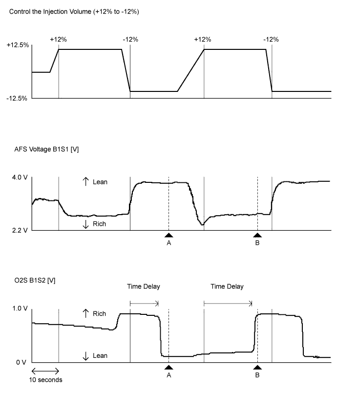
- *2: Control the Injection Volume (Idling after warming up)
- HINT:
- During the Active Test, air-fuel ratio feedback control and feedback learning are stopped.
Tester Display Measurement Item/Range Normal Condition Control the Injection Volume - ▲A ▲B Active Test operation -12% +12% AFS Voltage B1S1 3.86 V 2.98 V O2S B1S2 0.02 V 0.93 V - HINT:
- Usually, the value of AFS Voltage drops below 3.1 V when the control value for Control the Injection Volume is changed to +12%.
- Usually, the value of AFS Voltage changes to 3.4 V or higher when the control value for Control the Injection Volume is changed to -12%.
- Usually, the value of O2S changes to 0.55 V or higher when the control value for Control the Injection Volume is changed to +12%.
- Usually, the value of O2S drops below 0.4 V when the control value for Control the Injection Volume is changed to -12%.
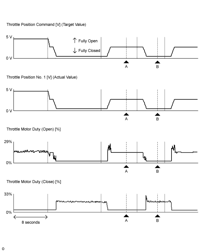
- *3: Control the ETCS Open/Close Fast Speed [Active Test for electrical throttle control system] (Ignition switch ON)
- HINT:
- Usually, Throttle Position Command (Target Value) and Throttle Position No. 1 (Actual Value) are almost the same.
- If any DTCs related to the ETCS are stored, this Active Test does not function.
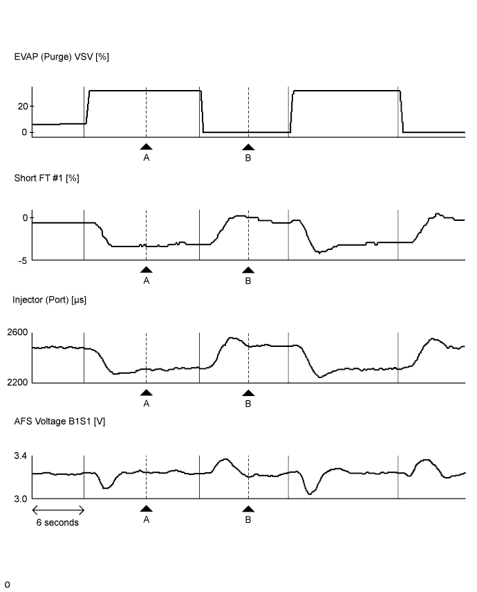
Tester Display Measurement Item/Range Normal Condition Control the ETCS Open/Close Fast Speed - ▲A ▲B Active Test operation Close Open Throttle Position Command 2.5 V 0.7 V Throttle Position No. 1 2.5 V 0.7 V Throttle Motor Duty (Open) 14% 0% Throttle Motor Duty (Close) 0% 13% - *4: Activate the VSV for Evap Control (Idling after warming up)
- HINT:
- Even when the Active Test is turned on (the purge VSV is opened 30%), air-fuel ratio feedback continues and control is performed so that the air-fuel ratio is the stoichiometric ratio. Therefore, by observing the change in "Short FT", it is possible to determine whether the purge VSV is actually open as well as the concentration of HC in the purge gas.
Tester Display Measurement Item/Range Normal Condition Activate the VSV for Evap Control - ▲A ▲B Active Test operation ON OFF EVAP (Purge) VSV 29.8% 0.0% Short FT #1 -2.4% 0.0% Injection (Port) 2.17 ms 2.30 ms AFS Voltage B1S1 3.35 V 3.34 V - HINT:
- The graphs and values above are for reference only because the fuel injection volume (compensation volume) varies depending on the HC density of the purge air from the canister.
- *5: Control the VVT Linear (Bank 1)

Tester Display Measurement Item/Range Normal Condition Control the VVT Linear (Bank 1) - ▲A ▲B Active Test operation* +30% -30% VVT Change Angle #1 40.6 DegFR 0.0 DegFR VVT OCV Duty #1 70.4% 10.4% VVT Aim Angle #1 40.4% 40.4% - HINT:
- *: Change the control value for Control the VVT Linear to +30% or -30% in increments of 5%.
- The Control the VVT Linear Active Test considers the value of VVT Aim Angle to be 0 and raises or lowers the duty ratio with respect to VVT Aim Angle.
- The sum of the control value for the Control the VVT Linear Active Test and the value of VVT Aim Angle is approximately equal to the value of VVT OCV Duty.
- When the control value for the Control the VVT Linear Active Test is changed a few times, there should not be a large discrepancy between VVT OCV Duty when the system starts advancing or retarding the timing and the rate of change of VVT Change Angle.
- *2: Control the Injection Volume (Idling after warming up)