Navigation System -- Operation Check |
| CHECK NAVIGATION SYSTEM NORMAL CONDITION |
If the symptom is applicable to any of the following, it is intended behavior, and not a malfunction.
Symptom Answer A longer route than expected is chosen. Depending on the road conditions, the extension module may determine that a longer route is quicker. Even when distance priority is high, the shortest route is not shown. Some routes may not be advised due to safety concerns. When the vehicle is put into motion immediately after the engine starts, the navigation system deviates from the correct position. If the vehicle starts before the navigation system activates, the system may not react. When driving on certain types of roads, especially new roads, the vehicle position deviates from the correct position. When the vehicle is driving on new roads not available on the hard disk drive, the system attempts to match it to another nearby road, causing the position mark to deviate. The following symptoms are not malfunctions, but are caused by errors inherent in the GPS, gyro sensor, speed sensor or extension module.
The current position mark may be displayed on a nearby parallel road.
Immediately after a fork in the road, the current vehicle position mark may be displayed on the wrong road.
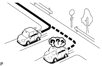
When the vehicle turns right or left at an intersection, the current vehicle position mark may be displayed on a nearby parallel road.
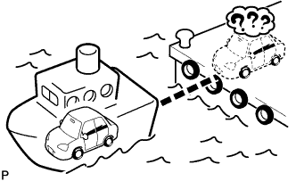
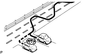
When the vehicle is carried, such as on a ferry, and the vehicle itself is not driving, the current vehicle position mark may be displayed in the position where the vehicle was until a measurement can be performed by the GPS.
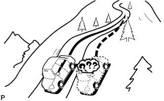
When the vehicle travels on a steep hill, the current vehicle position mark may deviate from the correct position.
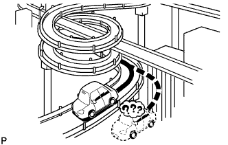
When the vehicle makes a continuous turn (e.g. 360, 720, 1080 degrees), the current vehicle position mark may deviate from the correct position.
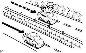
When the vehicle moves erratically, such as constant lane changes, the current vehicle position mark may deviate from the correct position.
When the ignition switch is turned to ACC or ON and the vehicle is turned on a turntable before parking, the current vehicle position mark may not indicate the correct direction. The same will occur when the vehicle comes out of the parking garage.
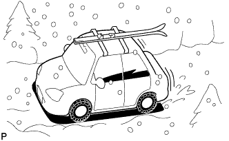
When the vehicle travels on a snowy road or a mountain path with tire chains installed or using a spare tire, the current vehicle position mark may deviate from the correct position.
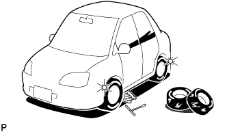
When the tires are changed, the current vehicle position mark may deviate from the correct position.
- HINT:
- A change in tire diameter may cause a speed sensor error.
- Performing "tire change" in calibration mode will allow the system to correct the current vehicle position faster.


 |
| CHECK PANEL & STEERING SWITCH |
- HINT:
- The radio and display receiver assembly panel switches and steering switches are checked in the following procedure.
- Illustrations may differ from the actual vehicle screen depending on the device settings and options. Therefore, some detailed areas may not be shown exactly the same as on the actual vehicle screen.
Enter diagnostic mode (COROLLA_ZRE142 RM0000011BU0JUX.html).
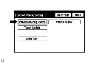
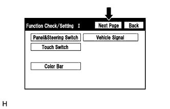
Select "Function Check/Setting" from the "Service Menu" screen.
Select "Panel & Steering Switch" from the "Function Check/Setting I" screen.
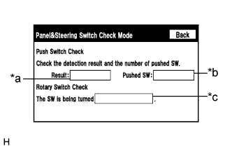
Panel & Steering Switch Check Mode
Screen Description Display Content *a: Switch condition "Pushed" is displayed when any switch is pushed *b: Number of switches pushed - Number of switches pushed at once is displayed
- If more than 3 switches are pushed at once, "More than 3" is displayed
*c: Rotary switch direction Direction of rotary switch is displayed Operate each switch and check that the switch conditions are correctly displayed.
- NOTICE:
- When the "SETUP" switch is pressed and held for 3 seconds or more, diagnostic mode will be canceled.
- Number of switches pushed at once is displayed
 |
 |
 |
| CHECK TOUCH SWITCH |
- HINT:
- The touch switches on the screen are checked in the following procedure.
- Illustrations may differ from the actual vehicle screen depending on the device settings and options. Therefore, some detailed areas may not be shown exactly the same as on the actual vehicle screen.
Enter diagnostic mode (COROLLA_ZRE142 RM0000011BU0JUX.html).
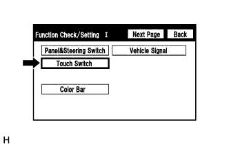
Select "Function Check/Setting" from the "Service Menu" screen.
Select "Touch Switch" from the "Function Check/Setting I" screen.
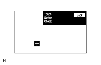
Touch Switch Check
Touch the display anywhere in the open area to perform the check when the "Touch Switch Check" screen is displayed.
- HINT:
- A "+" mark is displayed where the display is touched.
- The "+" mark remains on the display even after the finger is removed.
|
 |
 |
| CHECK COLOR BAR |
- HINT:
- The display color on the screen is checked in the following procedure.
- Illustrations may differ from the actual vehicle screen depending on the device settings and options. Therefore, some detailed areas may not be shown exactly the same as on the actual vehicle screen.
Enter diagnostic mode (COROLLA_ZRE142 RM0000011BU0JUX.html).
Select "Function Check/Setting" from the "Service Menu" screen.
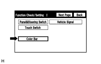
Select "Color Bar" from the "Function Check/Setting I" screen.
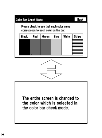
Color Bar Check Mode
Select a color bar from the "Color Bar Check Mode" screen.
Check the display color.
- HINT:
- The entire screen turns to the color or stripe selected.
- Touching the display will return to the "Color Bar Check Mode" screen.
|
 |
 |
| CHECK VEHICLE SIGNAL |
- HINT:
- Vehicle signals received by the radio and display receiver assembly are checked in the following procedure.
- Illustrations may differ from the actual vehicle screen depending on the device settings and options. Therefore, some detailed areas may not be shown exactly the same as on the actual vehicle screen.
Enter diagnostic mode (COROLLA_ZRE142 RM0000011BU0JUX.html).
Select "Function Check/Setting" from the "Service Menu" screen.
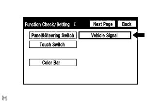
Select "Vehicle Signal" from the "Function Check/Setting I" screen.
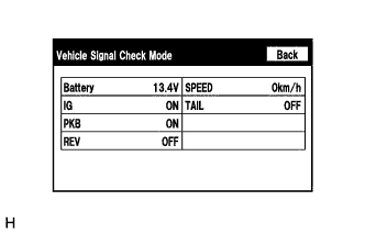
Vehicle Signal Check Mode
Screen Description Display Content Battery Battery voltage is displayed. IG Ignition switch ON/OFF state is displayed. PKB Parking brake ON/OFF state is displayed. REV Reverse signal ON/OFF state is displayed. SPEED Vehicle speed is displayed in km/h. TAIL Tail signal (Light control switch) ON/OFF state is displayed. - HINT:
- Only items sending vehicle signals will be displayed.
- This screen displays vehicle signals input to the radio and display receiver assembly.
- This screen is updated once per second when vehicle input signals change.
When the "Vehicle Signal Check Mode" screen is displayed, check all the vehicle signal conditions.
|
 |
 |
| CHECK MICROPHONE LEVEL |
- HINT:
- The microphone and microphone input level are checked in the following procedure.
- Illustrations may differ from the actual vehicle screen depending on the device settings and options. Therefore, some detailed areas may not be shown exactly the same as on the actual vehicle screen.
Enter diagnostic mode (COROLLA_ZRE142 RM0000011BU0JUX.html).
Select "Function Check/Setting" from the "Service Menu" screen.
Select "Next Page" from the "Function Check/Setting I" screen.
Select "EXT BOX" from the "Function Check/Setting II" screen.
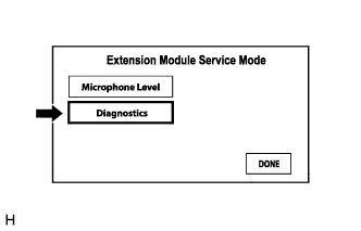
Select "Microphone Level" from the "Extension Module Service Mode" screen.
Microphone Level Test
Screen Description Display Content *a: Microphone input level meter Monitors the microphone input level every 0.1 seconds and displays the results in 8 different levels. When speaking into the microphone, check that the microphone input level meter changes according to the input level.
- HINT:
- The microphone is active at all times when this screen is displayed.
|
 |
 |
 |
 |
| CHECK DIAGNOSTICS |
- HINT:
- The connection condition of the USB device and each item (antenna) can be checked using the following procedure.
- Illustrations may differ from the actual vehicle screen depending on the device settings and options. Therefore, some detailed areas may not be shown exactly the same as on the actual vehicle screen.
Enter diagnostic mode (COROLLA_ZRE142 RM0000011BU0JUX.html).
Select "Function Check/Setting" from the "Service Menu" screen.
Select "Next Page" from the "Function Check/Setting I" screen.
Select "EXT BOX" from the "Function Check/Setting II" screen.
Select "Diagnostics" from the "Extension Module Service Mode" screen.
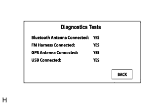
Diagnostics Tests
Check the connection condition of the USB device and each item (antenna) on the "Diagnostics Tests" screen.
- HINT:
- "YES" is displayed when the connection is good and "NO" is displayed when it is not.
- If "NO" is displayed for any of the item connected conditions, check each connection condition.
|
|
|
 |
 |
| ENTUNE RESET PROCEDURE |
Duplicate the problem symptom.
Check for DTCs and repair the systems for which any DTCs are output (COROLLA_ZRE142 RM0000011BU0JUX.html).
Check cellular phone compatibility.
Go to TIS "Bluetooth" Compatibility Portal and check if the cellular phone/vehicle is compatible.
If the phone is not compatible, recommend to the customer a compatible cellular phone.
Delete all paired devices from the cellular phone.
The procedure varies based on phone model. Contact the service provider or cellular phone manufacturer if assistance is required.
Remove the Entune app from the phone.
- NOTICE:
- Only perform this step if the customer is present and approves.
The procedure varies based on phone model. Contact the service provider or cellular phone manufacturer if assistance is required.
Reset the phone.
- NOTICE:
- Only perform this step if the customer is present and approves.
Turn off the phone and remove the battery for 15 seconds. For instructions on how to reset cellular devices, refer to the appropriate manufacturer's website.
Reinstall the Entune app on the phone. (If removed.)
The procedure varies based on phone model. Contact the service provider or cellular phone manufacturer if assistance is required.
Reset the extension module.
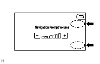
Display the "Navigation Prompt Volume" screen.
From the "Navigation Prompt Volume" screen, touch the corners of the screen in the following order: Upper right → Lower right → Upper right → Lower right → Upper right → Lower right.
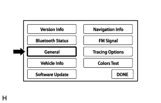
Select "General" from the Entune system status display screen.
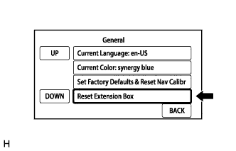
Select "Reset Extension Box" from the "General" screen, delete all personal data from the head unit.
- NOTICE:
- Only perform this step if the customer is present and approves.
- HINT:
- This will remove all personal data from the head unit.
- For a factory navigation system with a navigation receiver assembly, a successful Entune pairing must be completed prior to applications appearing on the head unit. This does not apply to a radio and display audio (extension module) type.
Disconnect the cable from the negative (-) battery terminal.
- NOTICE:
- After turning the ignition switch off, waiting time may be required before disconnecting the cable from the negative (-) battery terminal. Therefore, make sure to read the disconnecting the cable from the negative (-) battery terminal notices before proceeding with work (COROLLA_ZRE142 RM000000UYX0ETX.html).
Record all radio station presets.
Disconnect the cable from the negative (-) battery and leave it disconnected for 2 minutes.
Check if the problem symptom has been repaired.