Air Fuel Ratio Sensor Installation
INSTALL AIR FUEL RATIO SENSOR
INSTALL NO. 2 CYLINDER HEAD COVER
INSTALL OUTER COWL TOP PANEL (for TMC Made)
INSTALL OUTER COWL TOP PANEL (except TMC Made)
INSTALL WINDSHIELD WIPER MOTOR AND LINK ASSEMBLY
INSTALL COWL TOP VENTILATOR LOUVER LH
INSTALL CENTER NO. 1 COWL TOP VENTILATOR LOUVER
INSTALL HOOD TO COWL TOP SEAL
INSTALL FRONT WIPER ARM AND BLADE ASSEMBLY RH
INSTALL FRONT WIPER ARM AND BLADE ASSEMBLY LH
INSTALL FRONT WIPER ARM HEAD CAP
INSPECT FOR EXHAUST GAS LEAK
Air Fuel Ratio Sensor -- Installation |
| 1. INSTALL AIR FUEL RATIO SENSOR |
Using SST, install the air fuel ratio sensor.
- SST
- 09224-00010
- Torque:
- without SST:
- 44 N*m{449 kgf*cm, 32 ft.*lbf}
- with SST:
- 40 N*m{408 kgf*cm, 30 ft.*lbf}
- NOTICE:
- The "with SST" torque value is effective when SST is parallel to the torque wrench.
- The "with SST" torque value can be obtained by using a torque wrench with a fulcrum length of 300 mm (11.81 in.) and SST with a measurement of 30 mm (1.18 in.) (COROLLA_ZRE142 RM000000UYX0ETX.html).
Connect the air fuel ratio sensor connector and clamp.
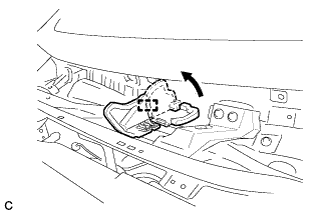
| 2. INSTALL NO. 2 CYLINDER HEAD COVER |
Engage the 4 clips to install the No. 2 cylinder head cover.
- NOTICE:
- Be sure to engage the clips securely.
- Do not apply excessive force or do not hit the cover to engage the clips. This may cause the cover to break.
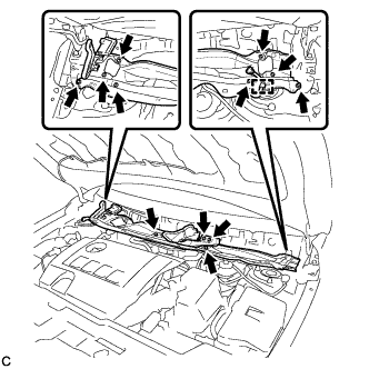
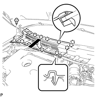
| 3. INSTALL OUTER COWL TOP PANEL (for TMC Made) |
Install the outer cowl top panel with the 12 bolts.
- Torque:
- 8.8 N*m{90 kgf*cm, 78 in.*lbf}
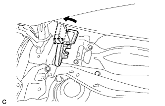
Engage the clamp.
Bend the water guard plate RH as shown in the illustration and engage the clamp.
| 4. INSTALL OUTER COWL TOP PANEL (except TMC Made) |
Install the outer cowl top panel with the 12 bolts.
- Torque:
- 8.8 N*m{90 kgf*cm, 78 in.*lbf}
Engage the clamp.
Bend the water guard plate RH as shown in the illustration, and engage the clamp.
Bend the No. 1 heater air duct splash shield seal as shown in the illustration, and engage the clamp.
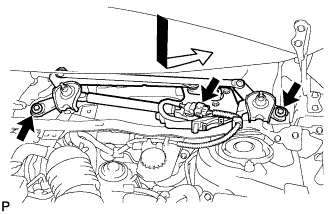
| 5. INSTALL WINDSHIELD WIPER MOTOR AND LINK ASSEMBLY |
Install the windshield wiper motor and link assembly with the 2 bolts.
- Torque:
- 5.5 N*m{56 kgf*cm, 49 in.*lbf}
Connect the connector.
| 6. INSTALL COWL TOP VENTILATOR LOUVER LH |
Engage the clip and 8 claws to install the cowl top ventilator louver LH.
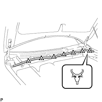
| 7. INSTALL CENTER NO. 1 COWL TOP VENTILATOR LOUVER |
Engage the clip and 14 claws to install the center No. 1 cowl top ventilator louver.
| 8. INSTALL HOOD TO COWL TOP SEAL |
Engage the 7 clips to install the hood to cowl top seal.
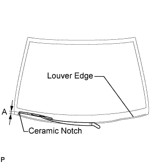
| 9. INSTALL FRONT WIPER ARM AND BLADE ASSEMBLY RH |
Operate the wiper and stop the windshield wiper motor at the automatic stop position.
Clean the wiper arm serrations.
When reinstalling:
Clean the wiper pivot serrations with a wire brush.
Install the front wiper arm and blade assembly RH with the nut to the position shown in the illustration.
- Torque:
- 26 N*m{265 kgf*cm, 19 ft.*lbf}
- HINT:
- Hold the arm hinge by hand while fastening the nut.
Area
| Measurement
|
A
| 27.5 to 42.5 mm (1.08 to 1.67 in.)
|
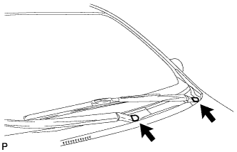
| 10. INSTALL FRONT WIPER ARM AND BLADE ASSEMBLY LH |
Operate the front wipers and stop the windshield wiper motor at the automatic stop position.
Clean the wiper arm serrations.
When reinstalling:
Clean the wiper pivot serrations with a wire brush.
Install the front wiper arm and blade assembly LH with the nut to the position shown in the illustration.
- Torque:
- 26 N*m{265 kgf*cm, 19 ft.*lbf}
- HINT:
- Hold the arm hinge by hand while fastening the nut.
Area
| Measurement
|
A
| 31.5 to 46.5 mm (1.24 to 1.83 in.)
|
Operate the front wipers while spraying washer fluid on the windshield glass. Make sure that the front wipers function properly and the wipers do not come into contact with the vehicle body.
| 11. INSTALL FRONT WIPER ARM HEAD CAP |
Install the 2 front wiper arm head caps.
| 12. INSPECT FOR EXHAUST GAS LEAK |