Air Conditioning System (For Manual Air Conditioning System) Heater Control Switch Circuit
DESCRIPTION
WIRING DIAGRAM
INSPECTION PROCEDURE
INSPECT NO. 3 HEATER CONTROL
CHECK HARNESS AND CONNECTOR (NO. 3 HEATER CONTROL - BATTERY)
CHECK HARNESS AND CONNECTOR (NO. 3 HEATER CONTROL - A/C AMPLIFIER)
AIR CONDITIONING SYSTEM (for Manual Air Conditioning System) - Heater Control Switch Circuit |
DESCRIPTION
The No. 3 heater control is powered through the HTR-IG fuse. The No. 3 heater control transmits operational signals of each switch to the A/C amplifier.
WIRING DIAGRAM
INSPECTION PROCEDURE
| 1.INSPECT NO. 3 HEATER CONTROL |
Measure the resistance.
Remove the No. 3 heater control.
Disconnect the connector from the No. 3 heater control.
Measure the resistance according to the value(s) in the table below.
- Standard Resistance:
Tester Connection
| Switch Condition
| Specified Condition
|
E65-2 (B) - E65-3 (A/C)
| A/C switch: LOCK
| Below 1 Ω
|
E65-2 (B) - E65-3 (A/C)
| A/C switch: FREE
| 10 kΩ or higher
|
E65-7 (B) - E65-8 (E)*1
| Air mix control dial: MAX HOT position
| Below 1 Ω
|
E65-7 (B) - E65-8 (E)*1
| Air mix control dial: except MAX HOT position
| 10 kΩ or higher
|
- *1: w/ PTC Heater Assembly
Check that the indicator light comes on.
Connect a positive (+) lead from the battery to terminal 3 and a negative (-) lead from the battery to terminal 4, and check that the indicator light comes on.
- OK:
- The indicator light comes on.
Check that the illumination comes on.
Connect a positive (+) lead from the battery to terminal 5 and a negative (-) lead from the battery to terminal 6, and check that the illumination comes on.
- OK:
- The illumination comes on.
Text in Illustration*A
| w/ PTC Heater Assembly
|
*a
| Component without harness connected
(No. 3 Heater Control)
|
| 2.CHECK HARNESS AND CONNECTOR (NO. 3 HEATER CONTROL - BATTERY) |
Measure the voltage according to the value(s) in the table below.
- Standard Voltage:
Tester Connection
| Switch Condition
| Specified Condition
|
E65-2 (B) - Body ground
| Ignition switch ON
| 11 to 14 V
|
E65-2 (B) - Body ground
| Ignition switch off
| Below 1 V
|
E65-7 (B) - Body ground*1
| Ignition switch ON
| 11 to 14 V
|
E65-7 (B) - Body ground*1
| Ignition switch off
| Below 1 V
|
- *1: w/ PTC Heater Assembly
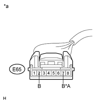
Text in Illustration*A
| w/ PTC Heater Assembly
|
*a
| Front view of wire harness connector
(to No. 3 Heater Control)
|
| | REPAIR OR REPLACE HARNESS OR CONNECTOR |
|
|
| 3.CHECK HARNESS AND CONNECTOR (NO. 3 HEATER CONTROL - A/C AMPLIFIER) |
Disconnect the connector from the A/C amplifier.
Measure the resistance according to the value(s) in the table below.
- Standard Resistance:
Tester Connection
| Condition
| Specified Condition
|
E65-3 (A/C) - E62-15 (A/C)*2
| Always
| Below 1 Ω
|
E65-4 (AIND) - E62-16 (LED)*2
| Always
| Below 1 Ω
|
E65-8 (E) - E63-14 (HEAT)*1
| Always
| Below 1 Ω
|
E65-3 (A/C) - E111-27 (A/C)*3
| Always
| Below 1 Ω
|
E65-4 (AIND) - E111-28 (LED)*3
| Always
| Below 1 Ω
|
E65-3 (A/C) - Body ground
| Always
| 10 kΩ or higher
|
E65-4 (AIND) - Body ground
| Always
| 10 kΩ or higher
|
E65-8 (E) - Body ground *1
| Always
| 10 kΩ or higher
|
- *1: w/ PTC Heater Assembly
- *2: except TMC Made 2AZ-FE
- *3: for TMC Made and except TMC Made 2ZR-FE
| | REPAIR OR REPLACE HARNESS OR CONNECTOR |
|
|