Air Conditioning System (For Manual Air Conditioning System) Headlight Signal Circuit
DESCRIPTION
WIRING DIAGRAM
INSPECTION PROCEDURE
INSPECT HEADLIGHT ASSEMBLY
CHECK HARNESS AND CONNECTOR (HEADLIGHT SIGNAL)
AIR CONDITIONING SYSTEM (for Manual Air Conditioning System) - Headlight Signal Circuit |
DESCRIPTION
The A/C amplifier receives headlight operational signals to determine the electrical load. The electrical load signals are used for controlling the number of the PTC heater elements to be heated.
WIRING DIAGRAM
INSPECTION PROCEDURE
| 1.INSPECT HEADLIGHT ASSEMBLY |
Check if the headlights come on when the light control switch is turned to the HEAD position.
- OK:
- The headlights come on.
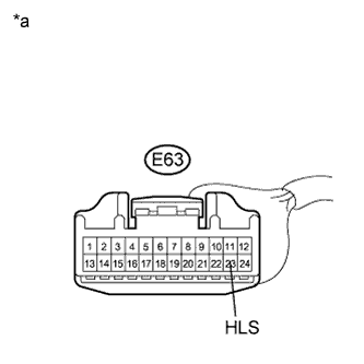
| 2.CHECK HARNESS AND CONNECTOR (HEADLIGHT SIGNAL) |
Disconnect the connector from the A/C amplifier.
Measure the voltage according to the value(s) in the table below.
- Standard Voltage:
Tester Connection
| Condition
| Specified Condition
|
E63-23 (HLS) - Body ground
| Light control switch: OFF
| 11 to 14 V
|
E63-23 (HLS) - Body ground
| Light control switch: HEAD
| Below 1 V
|
Text in Illustration*a
| Front view of wire harness connector
(to A/C Amplifier)
|
| | REPAIR OR REPLACE HARNESS OR CONNECTOR |
|
|