Air Conditioning System (For Manual Air Conditioning System) Recirculation Damper Servo Motor Circuit
DESCRIPTION
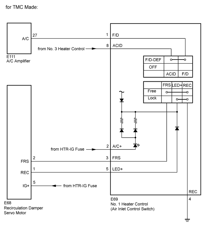
WIRING DIAGRAM
INSPECTION PROCEDURE
INSPECT RECIRCULATION DAMPER SERVO MOTOR
INSPECT NO. 1 HEATER CONTROL (AIR INLET CONTROL SWITCH)
CHECK HARNESS AND CONNECTOR (RECIRCULATION DAMPER SERVO MOTOR - BATTERY)
CHECK HARNESS AND CONNECTOR (NO. 1 HEATER CONTROL (AIR INLET CONTROL SWITCH) - BATTERY)
CHECK HARNESS AND CONNECTOR (NO. 1 HEATER CONTROL(AIR INLET CONTROL SWITCH) - BODY GROUND)
CHECK HARNESS AND CONNECTOR (NO. 1 HEATER CONTROL - RECIRCULATION DAMPER SERVO MOTOR)
CHECK HARNESS AND CONNECTOR (NO. 1 HEATER CONTROL - A/C AMPLIFIER)
AIR CONDITIONING SYSTEM (for Manual Air Conditioning System) - Recirculation Damper Servo Motor Circuit |
DESCRIPTION
The recirculation damper servo motor and No. 1 heater control (air inlet control switch) are powered through the HTR-IG fuse. Operating the No. 1 heater control (air inlet control switch) drives the recirculation damper servo motor to switch between "FRESH" and "RECIRCULATION".
WIRING DIAGRAM
INSPECTION PROCEDURE
- NOTICE:
- Inspect the fuses for circuits related to this system before performing the following inspection procedure.
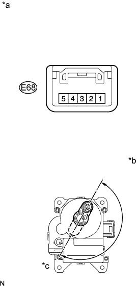
| 1.INSPECT RECIRCULATION DAMPER SERVO MOTOR |
Remove the recirculation damper servo motor.
Disconnect the connector from the recirculation damper servo motor.
Connect a positive (+) lead from the battery to terminal 5 and a negative (-) lead from the battery to terminal 2, then check that the arm turns to the "FRESH" side smoothly.
- OK:
- Lever turns to "FRESH" side smoothly.
Connect a positive (+) lead from the battery to terminal 5 and a negative (-) lead from the battery to terminal 1, then check that the arm turns to the "RECIRCULATION" side smoothly.
- OK:
- Lever turns to "RECIRCULATION" side smoothly.
Text in Illustration*a
| Component without harness connected
(Recirculation Damper Servo Motor)
|
*b
| Recirculation
|
*c
| Fresh
|
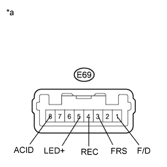
| 2.INSPECT NO. 1 HEATER CONTROL (AIR INLET CONTROL SWITCH) |
Remove the No. 1 heater control (air inlet control switch).
Disconnect the connector from the No. 1 heater control (air inlet control switch).
Measure the resistance according to the value(s) in the table below.
- Standard Resistance:
Tester Connection
| Switch Condition
| Specified Condition
|
E69-3 (FRS) - E69-4 (REC)
| Air inlet control switch: FREE
| Below 1 Ω
|
E69-3 (FRS) - E69-4 (REC)
| Air inlet control switch: LOCK
| 10 kΩ or higher
|
E69-1 (F/D) - E69-8 (ACID)
| Mode control dial: except Foot/DEF position and DEF position
| 10 kΩ or higher
|
E69-1 (F/D) - E69-8 (ACID)
| Mode control dial: Foot/DEF position or DEF position
| Below 1 Ω
|
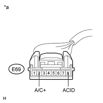
Check that the indicator light comes on.
Turn the heater control base (air inlet control switch) to LOCK.
Connect a positive (+) lead from the battery to terminal 2 and a negative (-) lead from the battery to terminal 4, and check that the indicator light comes on.
- OK:
- The indicator light comes on.
Check that the illumination comes on.
Connect a positive (+) lead from the battery to terminal 7 and negative (-) lead from the battery to terminal 6, and check that the illumination comes on.
- OK:
- The illumination comes on.
Text in Illustration*a
| Component without harness connected
(No. 1 Heater Control (Air Inlet Control Switch))
|
| 3.CHECK HARNESS AND CONNECTOR (RECIRCULATION DAMPER SERVO MOTOR - BATTERY) |
Measure the voltage according to the value(s) in the table below.
- Standard Voltage:
Tester Connection
| Switch Condition
| Specified Condition
|
E68-5 (IG+) - Body ground
| Ignition switch off
| Below 1 V
|
E68-5 (IG+) - Body ground
| Ignition switch ON
| 11 to 14 V
|
Text in Illustration*a
| Front view of wire harness connector
(to Recirculation Damper Servo Motor)
|
| | REPAIR OR REPLACE HARNESS OR CONNECTOR |
|
|
| 4.CHECK HARNESS AND CONNECTOR (NO. 1 HEATER CONTROL (AIR INLET CONTROL SWITCH) - BATTERY) |
Measure the voltage according to the value(s) in the table below.
- Standard Voltage:
Tester Connection
| Switch Condition
| Specified Condition
|
E69-2 (A/C+) - Body ground
| Ignition switch off
| Below 1 V
|
E69-2 (A/C+) - Body ground
| Ignition switch ON
| 11 to 14 V
|
E69-8 (ACID) - Body ground
| Ignition switch off
| Below 1 V
|
E69-8 (ACID) - Body ground
| Ignition switch ON
| 11 to 14 V
|
Text in Illustration*a
| Front view of wire harness connector
(to No. 1 Heater Control (Air Inlet Control Switch))
|
| | REPAIR OR REPLACE HARNESS OR CONNECTOR |
|
|
| 5.CHECK HARNESS AND CONNECTOR (NO. 1 HEATER CONTROL(AIR INLET CONTROL SWITCH) - BODY GROUND) |
Measure the resistance according to the value(s) in the table below.
- Standard Resistance:
Tester Connection
| Condition
| Specified Condition
|
E69-4 (REC) - Body ground
| Always
| Below 1 Ω
|
| | REPAIR OR REPLACE HARNESS OR CONNECTOR |
|
|
| 6.CHECK HARNESS AND CONNECTOR (NO. 1 HEATER CONTROL - RECIRCULATION DAMPER SERVO MOTOR) |
Measure the resistance according to the value(s) in the table below.
- Standard Resistance:
Tester Connection
| Condition
| Specified Condition
|
E69-3 (FRS) - E68-2 (FRS)
| Always
| Below 1 Ω
|
E69-5 (LED+) - E68-1 (REC)
| Always
| Below 1 Ω
|
E69-3 (FRS) - Body ground
| Always
| 10 kΩ or higher
|
E69-5 (LED+) - Body ground
| Always
| 10 kΩ or higher
|
| | REPAIR OR REPLACE HARNESS OR CONNECTOR |
|
|
| 7.CHECK HARNESS AND CONNECTOR (NO. 1 HEATER CONTROL - A/C AMPLIFIER) |
Disconnect the connector from the A/C amplifier.
Measure the resistance according to the value(s) in the table below.
- Standard Resistance:
Tester Connection
| Condition
| Specified Condition
|
E69-1 (F/D) - E62-15 (A/C)*1
| Always
| Below 1 Ω
|
E69-1 (F/D) - E111-27 (A/C)*2
| Always
| Below 1 Ω
|
E69-1 (F/D) - Body ground
| Always
| 10 kΩ or higher
|
- *1: except TMC Made 2AZ-FE
- *2: for TMC Made and except TMC Made 2ZR-FE
| | REPAIR OR REPLACE HARNESS OR CONNECTOR |
|
|