INSTALL NO. 1 ROOF WIRE (for TMMC Made without Sliding Roof)
INSTALL NO. 3 ROOF SILENCER PAD (for TMC Made without Sliding Roof)
INSTALL NO. 1 ROOF SILENCER PAD (for TMC Made without Sliding Roof)
INSTALL NO. 1 ROOF SILENCER PAD (for TMMC Made without Sliding Roof)
INSTALL SHIFT LOCK CONTROL UNIT ASSEMBLY (for Automatic Transaxle)
CONNECT TRANSMISSION CONTROL CABLE ASSEMBLY (for Automatic Transaxle)
CONNECT TRANSMISSION CONTROL CABLE ASSEMBLY (for Manual Transaxle)
ADJUST TRANSMISSION CONTROL SELECT CABLE (for Manual Transaxle)
INSTALL CENTER NO. 1 INSTRUMENT CLUSTER FINISH PANEL ASSEMBLY (for Automatic Transaxle)
INSTALL CENTER NO. 1 INSTRUMENT CLUSTER FINISH PANEL ASSEMBLY (for Manual Transaxle)
INSTALL SHIFT LEVER KNOB SUB-ASSEMBLY (for Automatic Transaxle)
INSTALL SHIFT LEVER KNOB SUB-ASSEMBLY (for Manual Transaxle)
CONNECT CABLE TO NEGATIVE BATTERY TERMINAL (for Manual Seat)
Roof Headlining -- Installation |
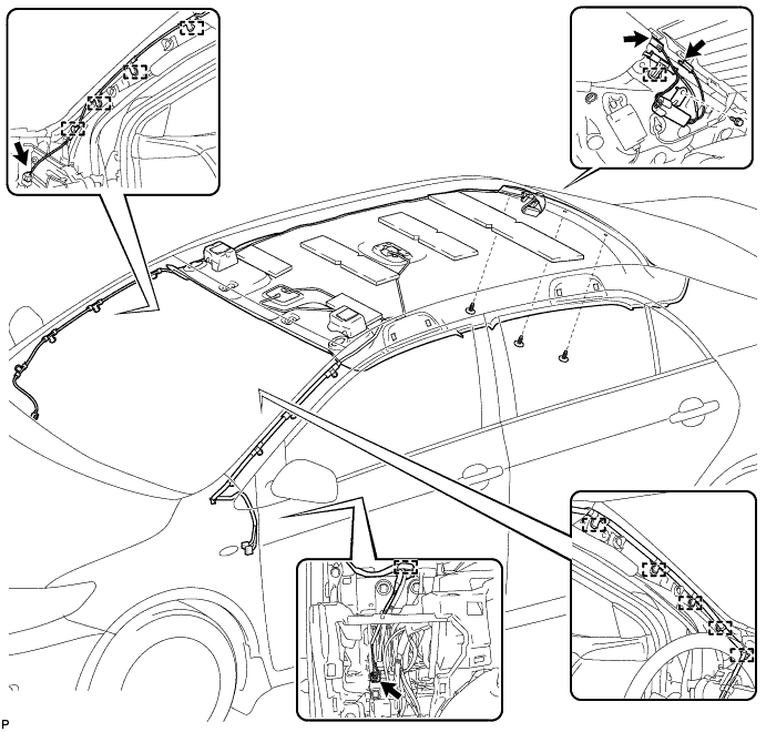
| 1. INSTALL NO. 1 ROOF WIRE (w/ Sliding Roof) |
Temporarily install the No. 1 roof wire aligned with the markings on the roof headlining assembly.
Apply adhesive tape to the locations shown in the illustration.
Engage the 3 clamps.

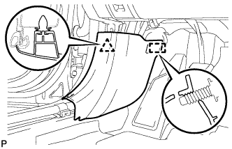
| 2. INSTALL NO. 1 ROOF WIRE (for TMMC Made without Sliding Roof) |
Temporarily install the No. 1 roof wire aligned with the markings on the roof headlining assembly.
Apply adhesive tape to the locations shown in the illustration.
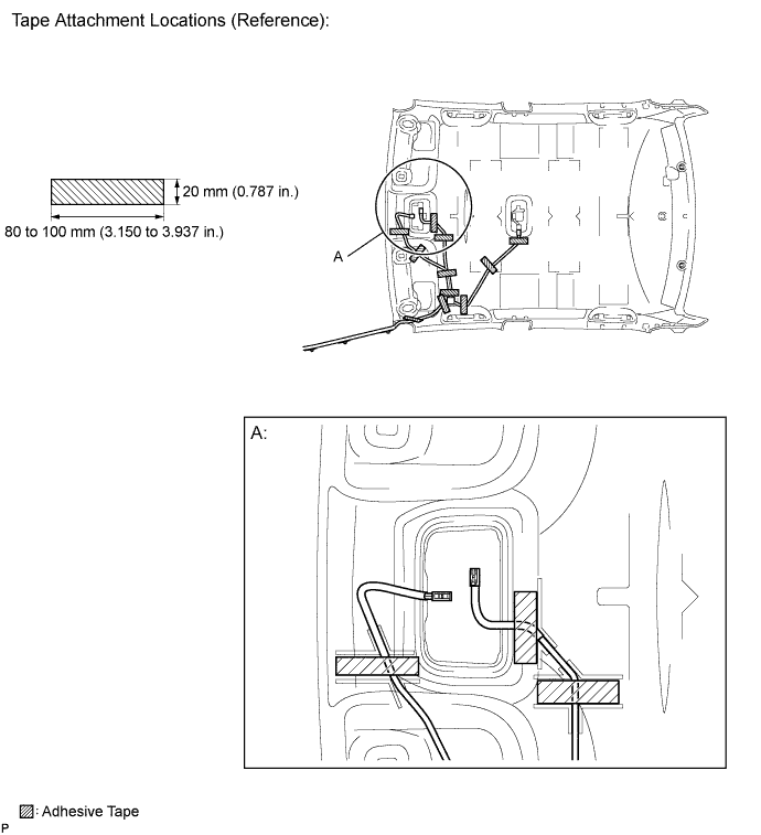
| 3. INSTALL NO. 1 ROOF WIRE (for TMC Made without Sliding Roof) |
Temporarily install the No. 1 roof wire aligned with the markings on the roof headlining assembly.
Apply adhesive tape to the locations shown in the illustration.
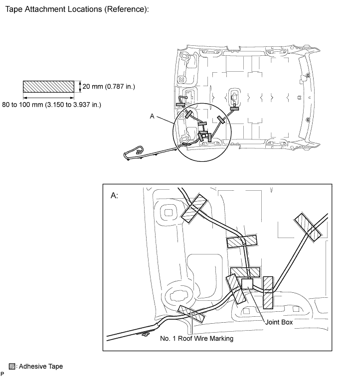
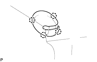
- HINT:
- Align the No. 1 roof wire marking in area A in the illustration with the reference point on the roof headlining assembly.
- Align the joint box with the markings on the roof headlining assembly.
| 4. INSTALL AMPLIFIER ANTENNA ASSEMBLY (w/ Sliding Roof) |
Temporarily install the amplifier antenna assembly, aligning it with the marking on the roof headlining assembly.
Attach pieces of adhesive tape and clamp in the sequence shown in the illustration, aligning them with the markings on the roof headlining assembly.
- NOTICE:
- To prevent noise, be sure to attach adhesive tape securely.
- HINT:
- Adjust the length of the amplifier antenna assembly at point A shown in the illustration.
Insert the amplifier antenna assembly into the slit on the roof headlining assembly to install the amplifier antenna assembly to the roof headlining assembly.

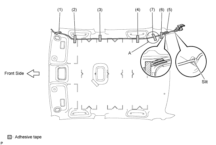
| 5. INSTALL AMPLIFIER ANTENNA ASSEMBLY (w/o Sliding Roof) |
Temporarily install the amplifier antenna assembly, aligning it with the marking on the roof headlining assembly.
Attach pieces of adhesive tape in the sequence shown in the illustration, aligning them with the markings on the roof headlining assembly.
- NOTICE:
- To prevent noise, be sure to attach adhesive tape securely.
- HINT:
- Adjust the length of the amplifier antenna assembly at point A shown in the illustration.
Insert the amplifier antenna assembly into the slit on the roof headlining assembly to install the amplifier antenna assembly to the roof headlining assembly.
| 6. INSTALL ROOF SIDE RAIL SILENCER PAD LH (w/ Sliding Roof) |
Align the markings on the roof headlining assembly with the roof side rail silencer pad LH and install the silencer pad using hot-melt glue or double-sided tape as shown in the illustration.

| 7. INSTALL ROOF SIDE RAIL SILENCER PAD RH (w/ Sliding Roof) |
- HINT:
- Use the same procedure as for the LH side.
| 8. INSTALL ROOF SIDE RAIL SILENCER PAD LH (w/o Sliding Roof) |
Align the markings on the roof headlining assembly with the roof side rail silencer pad LH and install the silencer pad using hot-melt glue or double-sided tape as shown in the illustration.

| 9. INSTALL ROOF SIDE RAIL SILENCER PAD RH (w/o Sliding Roof) |
- HINT:
- Use the same procedure as for the LH side.
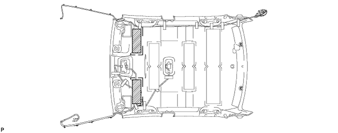
| 10. INSTALL NO. 3 ROOF SILENCER PAD (for TMC Made without Sliding Roof) |
Align the markings on the roof headlining assembly with the No. 3 roof silencer pad and install the silencer pad using hot-melt glue or double-sided tape as shown in the illustration.
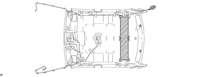
| 11. INSTALL NO. 2 ROOF SILENCER PAD (w/o Sliding Roof) |
Align the markings on the roof headlining assembly with the 2 No. 2 roof silencer pads and install the silencer pads using hot-melt glue or double-sided tape as shown in the illustration.
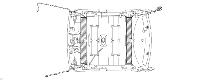
| 12. INSTALL NO. 1 ROOF SILENCER PAD (for TMC Made without Sliding Roof) |
Align the markings on the roof headlining assembly with the 2 No. 1 roof silencer pads and install the silencer pads using hot-melt glue or double-sided tape as shown in the illustration.
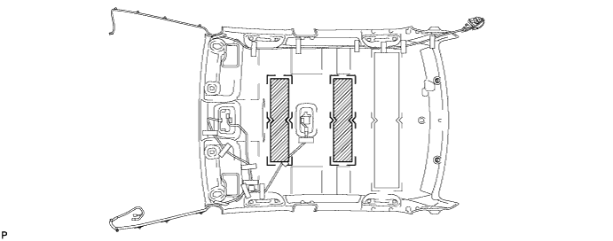
| 13. INSTALL NO. 1 ROOF SILENCER PAD (for TMMC Made without Sliding Roof) |
Align the markings on the roof headlining assembly with the 2 No. 1 roof silencer pads and install the silencer pads using hot-melt glue or double-sided tape as shown in the illustration.
| 14. INSTALL ROOF HEADLINING ASSEMBLY (w/ Sliding Roof) |
Pass the roof headlining assembly into the vehicle through the front passenger door.
- NOTICE:
- Do not damage the roof headlining assembly or body interior.
 |
Install the 3 clips.
Connect the sliding roof drive gear connector.
Connect the amplifier antenna assembly and install the bolt to the rear pillar RH.
- Torque:
- 8.4 N*m{86 kgf*cm, 74 in.*lbf}
Connect the amplifier antenna assembly connectors and engage the clamp to the rear pillar RH.
Connect the amplifier antenna assembly connector and engage each clamp to the front pillar RH.
Connect the No. 1 roof wire connector and engage each clamp to the front pillar LH.
Connect the No. 1 roof wire connectors to the instrument panel junction block.

w/ EC Mirror:
Connect the connector.
| 15. INSTALL ROOF HEADLINING ASSEMBLY (w/o Sliding Roof) |
Pass the roof headlining assembly into the vehicle through the front passenger door.
- NOTICE:
- Do not damage the roof headlining assembly or body interior.
 |
Install the 3 clips.
Connect the amplifier antenna assembly and install the bolt to the rear pillar RH.
- Torque:
- 8.4 N*m{86 kgf*cm, 74 in.*lbf}
Connect the amplifier antenna assembly connectors and engage the clamp to the rear pillar RH.
Connect the amplifier antenna assembly connector and engage each clamp to the front pillar RH.
Connect the No. 1 roof wire connector and engage each clamp to the front pillar LH.
Connect the No. 1 roof wire connectors to the instrument panel junction block.
| 16. INSTALL SUN ROOF OPENING TRIM MOULDING (w/ Sliding Roof) |
Align the alignment mark on the inner surface of the opening trim moulding with the notch of the roof headlining, and install the sun roof opening trim moulding so that the alignment mark on the opening trim is on the right side of the vehicle as shown in the illustration.
- NOTICE:
- After installation, check that the corners fit correctly.
 |
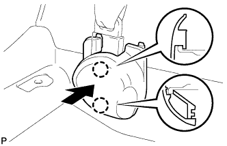
| 17. INSTALL VISOR HOLDER |
Engage the 2 claws.
 |
Push in the visor holder as shown in the illustration.
- HINT:
- Use the same procedure for the RH side and LH side.
| 18. INSTALL INNER REAR VIEW MIRROR COVER (w/ EC Mirror) |
Engage the 6 claws and temporarily install the inner rear view mirror cover.
 |
Slide the inner rear view mirror cover and engage the 2 claws as shown in the illustration to install the cover.
 |
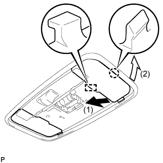
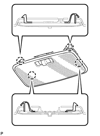
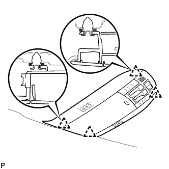
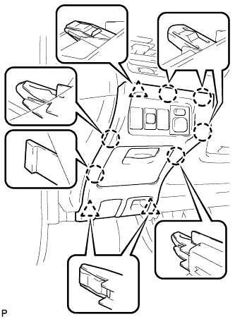
| 19. INSTALL NO. 1 ROOM LIGHT ASSEMBLY |
Engage the guide and claw in the order shown in the illustration, and install the room light cover.
- HINT:
- Use the same procedure for the RH side and the LH side.
 |
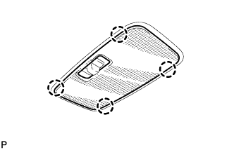
Engage the 4 claws and install the lens cover.
 |
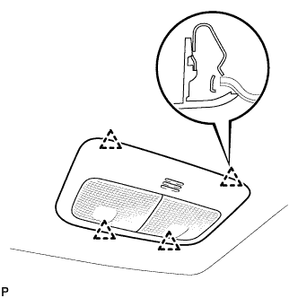
Engage the 4 claws and install the room light switch base to the No. 1 room light assembly.
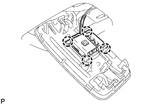 |
Engage the 4 claws and install the No. 1 room light assembly.
 |
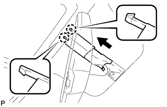
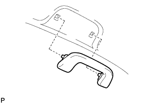
| 20. INSTALL ASSIST GRIP SUB-ASSEMBLY |
Assemble the assist grip sub-assembly as shown in the illustration.
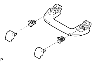 |
Install the assist grip sub-assembly.
- HINT:
- Use the same procedure for the other 3 assist grips.
 |
| 21. INSTALL VISOR ASSEMBLY LH |
Install the 2 clips to the visor assembly LH.
Engage the 2 clips and install the visor assembly LH.
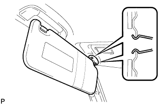 |
Engage the 4 claws and install a new visor bracket cover.
 |
| 22. INSTALL VISOR ASSEMBLY RH |
- HINT:
- Use the same procedure as for the LH side.
| 23. INSTALL MAP LIGHT ASSEMBLY (w/ Sliding Roof) |
Connect the connector.
Engage the 4 clips and install the map light assembly.
 |
| 24. INSTALL MAP LIGHT ASSEMBLY (w/o Sliding Roof) |
Connect the connector.
Engage the 4 clips and install the map light assembly.
 |
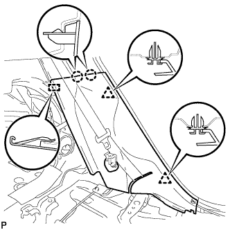
| 25. INSTALL ROOF SIDE INNER GARNISH ASSEMBLY LH |
Engage the 2 guides and 4 clips, and install the roof side inner garnish assembly LH.
 |
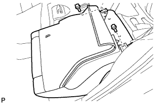
| 26. INSTALL ROOF SIDE INNER GARNISH BOARD LH |
Engage the 2 guides and 2 claws, and install the roof side inner garnish board LH.
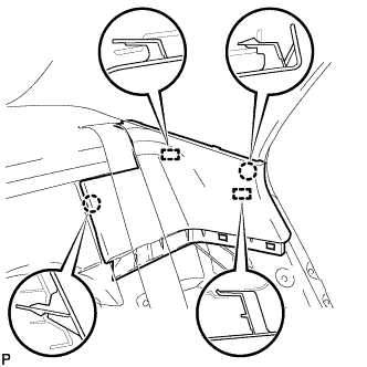 |
| 27. INSTALL REAR SEAT SIDE GARNISH LH |
Engage the 2 claws, 2 clips and guide, and install the rear seat side garnish LH.
 |
| 28. INSTALL ROOF SIDE INNER GARNISH ASSEMBLY RH |
- HINT:
- Use the same procedure as for the LH side.
| 29. INSTALL ROOF SIDE INNER GARNISH BOARD RH |
- HINT:
- Use the same procedure as for the LH side.
| 30. INSTALL REAR SEAT SIDE GARNISH RH |
- HINT:
- Use the same procedure as for the LH side.
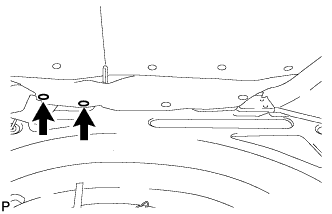
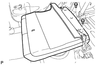
| 31. INSTALL REAR SEATBACK ASSEMBLY LH |
Place the rear seatback assembly LH in the cabin.
- NOTICE:
- Be careful not to damage the vehicle body.
Install the rear seatback assembly LH with the 2 bolts.
- Torque:
- 18 N*m{184 kgf*cm, 13 ft.*lbf}
 |
Install the 2 rear seatback clips.
 |
| 32. INSTALL REAR SEATBACK ASSEMBLY RH |
Place the rear seatback assembly RH in the cabin.
- NOTICE:
- Be careful not to damage the vehicle body.
Install the rear seatback assembly RH with the 2 bolts.
- Torque:
- 18 N*m{184 kgf*cm, 13 ft.*lbf}
 |
Install the 2 rear seatback clips.
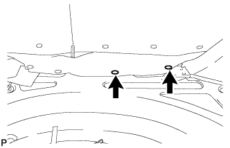 |
| 33. INSTALL REAR SEAT CUSHION ASSEMBLY |
Attach the rear hook of the seat cushion to the seatback.
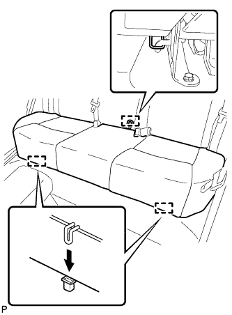 |
Attach the 2 front hooks of the seat cushion to the vehicle body.
Confirm that the seat cushion is firmly installed.
- NOTICE:
- When installing the seat cushion, make sure that the seat belt buckle is not under the seat cushion.
| 34. INSTALL REAR SEAT CENTER HEADREST ASSEMBLY |
| 35. INSTALL REAR SEAT HEADREST ASSEMBLY LH |
| 36. INSTALL REAR SEAT HEADREST ASSEMBLY RH |
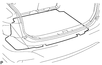
| 37. INSTALL SPARE WHEEL COVER |
Install the spare wheel cover.
 |
| 38. INSTALL UPPER CENTER PILLAR GARNISH LH |
Engage the clip.
 |
Install the upper center pillar garnish LH with the 2 screws.
| 39. INSTALL LOWER CENTER PILLAR GARNISH LH |
Engage the 2 claws and 2 clips, and install the lower center pillar garnish LH.
 |
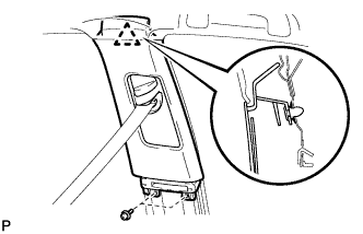
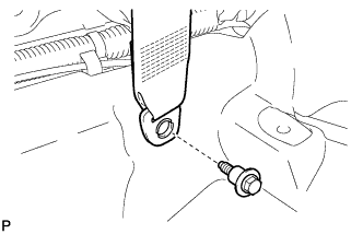
| 40. CONNECT FRONT SEAT OUTER BELT ASSEMBLY LH |
Install the floor end of the front seat outer belt assembly with the bolt.
- Torque:
- 41 N*m{420 kgf*cm, 30 ft.*lbf}
 |
Check if the ELR locks.
- NOTICE:
- The check should be performed with the outer belt assembly installed.
With the belt assembly installed, check that the belt locks when it is pulled out quickly.
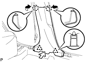
| 41. INSTALL LAP BELT OUTER ANCHOR COVER (for LH Side) |
Engage the 3 claws and install the lap belt outer anchor cover.
 |
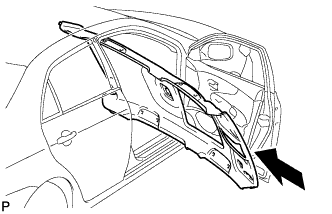
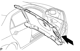
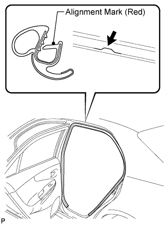
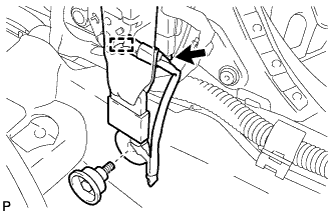
| 42. INSTALL REAR DOOR OPENING TRIM WEATHERSTRIP LH |
for TMC Made:
Align the alignment mark (pink) on the weatherstrip and the protruding portion on the body indicated by the arrow in the illustration, and install the rear door opening trim weatherstrip LH.
- NOTICE:
- After installation, check that the corners fit correctly.
 |
for TMMC Made:
Align the alignment mark (red) on the weatherstrip and the protruding portion on the body indicated by the arrow in the illustration, and install the rear door opening trim weatherstrip LH.
- NOTICE:
- After installation, check that the corners fit correctly.
 |
| 43. INSTALL REAR DOOR SCUFF PLATE LH |
Engage the 6 claws and install the rear door scuff plate LH.
 |
| 44. INSTALL UPPER CENTER PILLAR GARNISH RH |
- HINT:
- Use the same procedure as for the LH side.
| 45. CONNECT FRONT SEAT OUTER BELT ASSEMBLY RH |
Install the floor end of the front seat outer belt assembly with the front seat belt anchor base.
- Torque:
- 41 N*m{420 kgf*cm, 30 ft.*lbf}
 |
Engage the clamp.
Connect the connector.
Check if the ELR locks.
- NOTICE:
- The check should be performed with the outer belt assembly installed.
With the belt assembly installed, check that the belt locks when it is pulled out quickly.
| 46. INSTALL LOWER CENTER PILLAR GARNISH RH |
- HINT:
- Use the same procedure as for the LH side.
| 47. INSTALL LAP BELT OUTER ANCHOR COVER (for RH Side) |
Engage the 2 guides.
 |
Engage the 2 claws and install the lap belt outer anchor cover.
 |
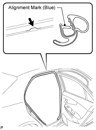
| 48. INSTALL REAR DOOR OPENING TRIM WEATHERSTRIP RH |
Align the alignment mark (blue) on the weatherstrip and the protruding portion on the body indicated by the arrow in the illustration, and install the rear door opening trim weatherstrip RH.
- NOTICE:
- After installation, check that the corners fit correctly.
 |
| 49. INSTALL REAR DOOR SCUFF PLATE RH |
- HINT:
- Use the same procedure as for the LH side.
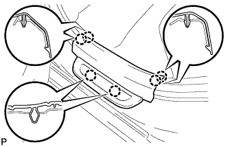
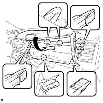
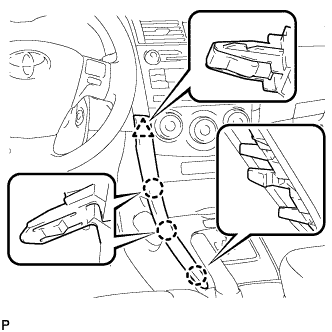
| 50. INSTALL UPPER INSTRUMENT PANEL SUB-ASSEMBLY |
When using a new upper instrument panel sub-assembly:
Immediately before installing the upper instrument panel sub-assembly, twist and cut off the portions shown in the illustration (joints for moulding).
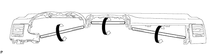
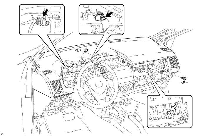
Install the upper instrument panel sub-assembly and engage the 5 claws.
- NOTICE:
- When installing the upper instrument panel sub-assembly, be careful not to damage it or the steering wheel assembly.
- Do not allow the wire harness to get caught in the claws.

Engage the 5 clips and 4 guides.

Install the 2 screws <B>.
Install the passenger airbag bolt <A>.
- Torque:
- 20 N*m{204 kgf*cm, 15 ft.*lbf}
Connect each connector.
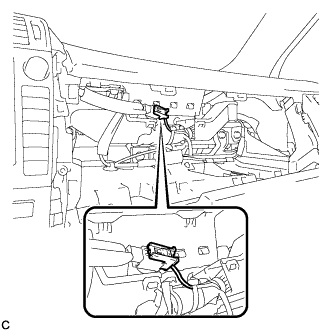
| 51. CONNECT INSTRUMENT PANEL WIRE ASSEMBLY |
Check that the ignition switch is off.
Check that the cable is disconnected from the negative (-) battery terminal.
- CAUTION:
- Wait at least 90 seconds after disconnecting the cable from the negative (-) battery terminal to disable the SRS system.
Connect the connector.
- NOTICE:
- When connecting the airbag connector, take care not to damage the airbag wire harness.
 |
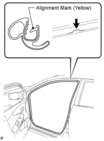
| 52. INSTALL FRONT DOOR OPENING TRIM WEATHERSTRIP LH |
Align the alignment mark (yellow) on the weatherstrip and the protruding portion on the body indicated by the arrow in the illustration, and install the front door opening trim weatherstrip LH.
- NOTICE:
- After installation, check that the corners fit correctly.
 |
| 53. INSTALL COWL SIDE TRIM BOARD LH |
Engage the guide and clip, and install the cowl side trim board LH.
 |
| 54. INSTALL FRONT DOOR SCUFF PLATE LH |
Engage the 8 claws and install the front door scuff plate LH.
 |
| 55. INSTALL LOWER INSTRUMENT PANEL FINISH PANEL ASSEMBLY |
Connect each connector.
Engage the 6 claws and 3 clips to install the lower instrument panel finish panel assembly.
 |
| 56. INSTALL FRONT DOOR OPENING TRIM WEATHERSTRIP RH |
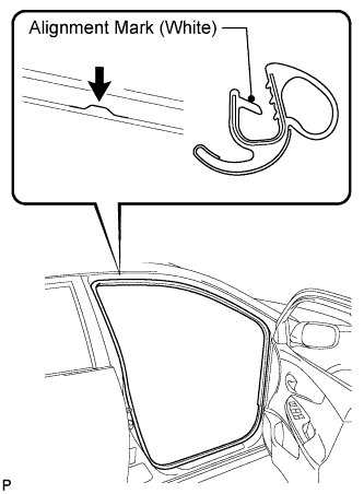
Align the alignment mark (white) on the weatherstrip and the protruding portion on the body indicated by the arrow in the illustration, and install the front door opening trim weatherstrip RH.
- NOTICE:
- After installation, check that the corners fit correctly.
 |
| 57. INSTALL COWL SIDE TRIM BOARD RH |
- HINT:
- Use the same procedure as for the LH side.
| 58. INSTALL FRONT DOOR SCUFF PLATE RH |
- HINT:
- Use the same procedure as for the LH side.
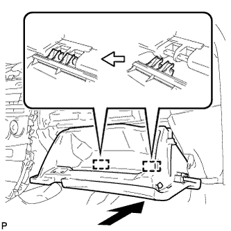
| 59. INSTALL NO. 1 INSTRUMENT PANEL BOX DOOR SUB-ASSEMBLY |
Engage the 3 claws and 4 clips.
 |
Install the No. 1 instrument panel box door sub-assembly with the screw <B>.
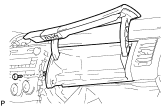 |
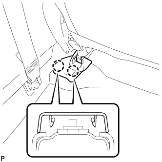
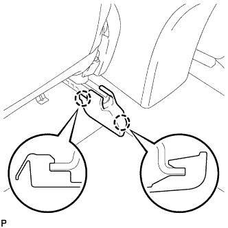
| 60. INSTALL GLOVE COMPARTMENT DOOR ASSEMBLY |
Insert the glove compartment door assembly horizontally and engage the 2 hinges.
- NOTICE:
- Engaging the hinges from the above will deform the hinges. Be sure to install the glove compartment door assembly horizontally.
 |
Bend portions (A) and (B) in the direction indicated by the arrows in the illustration to engage the 2 stoppers.
 |
Engage the claw, connect the glove compartment door stopper, and install the glove compartment door assembly.
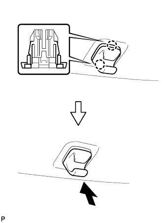
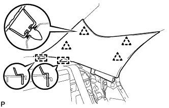
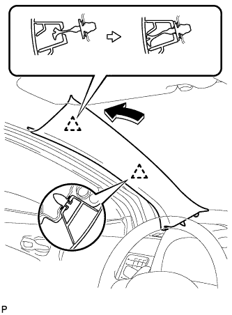
| 61. INSTALL FRONT PILLAR GARNISH LH |
Remove the protective cover.
 |
Make sure that the front pillar garnish clip is not damaged.
- NOTICE:
- If there is any damage, replace the garnish clip with a new one.
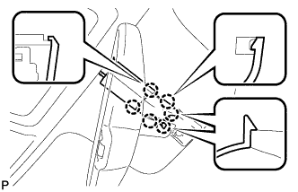
- When a garnish clip is being replaced, make sure to install it in the direction shown in the illustration.
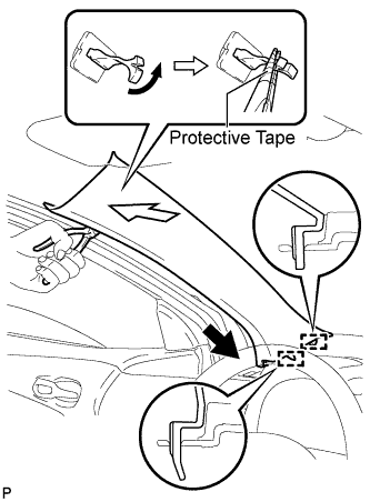 |
Engage the 2 guides.
Turn the end of the front pillar garnish clip 90° with needle-nosed pliers and install it to the front pillar garnish LH.
- HINT:
- Tape the tips of the needle-nosed pliers before use.
Engage the 2 clips to install the front pillar garnish LH.
 |
| 62. INSTALL FRONT PILLAR GARNISH RH |
- HINT:
- Use the same procedure as for the LH side.
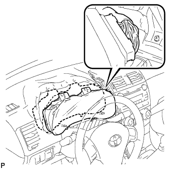
| 63. INSTALL COMBINATION METER ASSEMBLY |
Connect the connector and temporarily install the combination meter assembly.
- NOTICE:
- When installing the combination meter assembly, do not damage the upper instrument panel sub-assembly or combination meter assembly.
 |
Engage the 2 guides.
- NOTICE:
- When installing the combination meter assembly, be careful not to break the guide.
- When installing the combination meter assembly, insert the guides securely into the holes on the upper instrument panel sub-assembly.
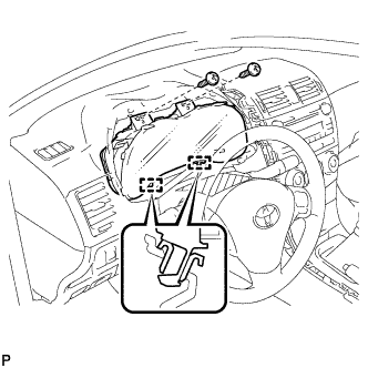 |
Install the combination meter assembly with the 2 screws.
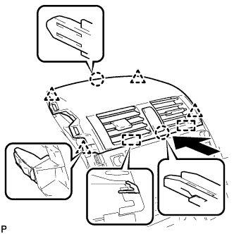
| 64. INSTALL INSTRUMENT CLUSTER FINISH PANEL ASSEMBLY |
Engage the guide, claw and 3 clips, and install the instrument cluster finish panel assembly.
 |
Remove the applied protective tape on the steering column cover.
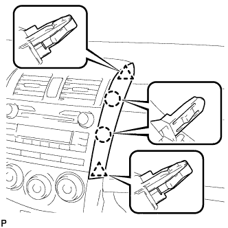
| 65. INSTALL CENTER INSTRUMENT PANEL REGISTER ASSEMBLY |
Connect each connector.
w/o Daytime Running Light:
Engage the clamp.
Engage the 2 guides, 2 claws and 4 clips, and install the center instrument panel register assembly.
 |
| 66. INSTALL INSTRUMENT PANEL FINISH PANEL END LH |
Engage the 2 claws and 2 clips, and then install the instrument panel finish panel end LH.
 |
| 67. INSTALL INSTRUMENT PANEL FINISH PANEL END RH |
Engage the 2 claws and 2 clips, and then install the instrument panel finish panel end RH.
 |
| 68. INSTALL SHIFT LOCK CONTROL UNIT ASSEMBLY (for Automatic Transaxle) |
for U341E: (COROLLA_ZRE142 RM0000020U504NX_01_0001.html)
| 69. INSTALL SHIFT LEVER ASSEMBLY (for Manual Transaxle) |
for E351: (COROLLA_ZRE142 RM000001VZN051X_01_0001.html)
| 70. CONNECT TRANSMISSION CONTROL CABLE ASSEMBLY (for Automatic Transaxle) |
for U341E: (COROLLA_ZRE142 RM0000020U504NX_01_0002.html)
| 71. CONNECT TRANSMISSION CONTROL CABLE ASSEMBLY (for Manual Transaxle) |
for E351: (COROLLA_ZRE142 RM000001VZN051X_01_0002.html)
| 72. ADJUST TRANSMISSION CONTROL SELECT CABLE (for Manual Transaxle) |
for E351: (COROLLA_ZRE142 RM000002YVY02OX_01_0001.html)
| 73. INSTALL CONSOLE BOX ASSEMBLY (for Automatic Transaxle) |
Install the 2 screws.
Install the console box assembly with the 2 bolts and 2 screws.
| 74. INSTALL CONSOLE BOX ASSEMBLY (for Manual Transaxle) |
Install the 2 screws.
Install the console box assembly with the 2 bolts.
| 75. INSTALL CONSOLE BOX CARPET |
Install the console box carpet.
| 76. INSTALL UPPER CONSOLE PANEL SUB-ASSEMBLY |
Engage the 6 clips and 2 guides to install the upper console panel sub-assembly.
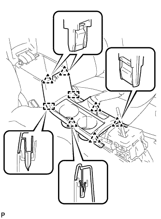 |
| 77. INSTALL FRONT NO. 1 CONSOLE BOX INSERT |
Engage the guide.
 |
Engage the 3 claws and install the front No. 1 console box insert.
| 78. INSTALL FRONT NO. 2 CONSOLE BOX INSERT |
Engage the guide.
 |
Engage the 3 claws and install the front No. 2 console box insert.
| 79. INSTALL INSTRUMENT PANEL BOX ASSEMBLY |
Connect the connector.
Engage the 2 claws.
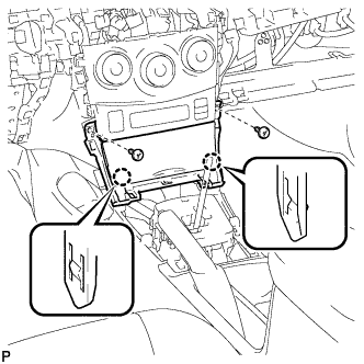 |
Install the instrument panel box assembly with the 2 screws <B>.
| 80. INSTALL CENTER NO. 1 INSTRUMENT CLUSTER FINISH PANEL ASSEMBLY (for Automatic Transaxle) |
Engage the guide.
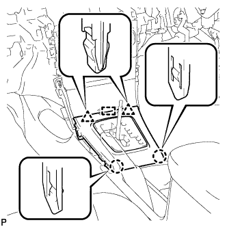 |
Engage the 2 claws and 2 clips, and install the center No.1 instrument cluster finish panel assembly.
| 81. INSTALL CENTER NO. 1 INSTRUMENT CLUSTER FINISH PANEL ASSEMBLY (for Manual Transaxle) |
Engage the guide.
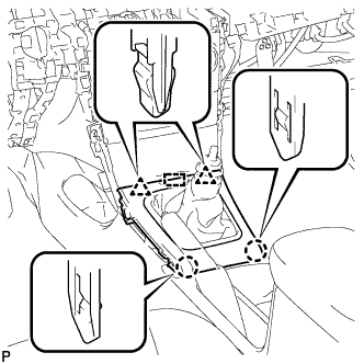 |
Engage the 2 claws and 2 clips, and install the center No.1 instrument cluster finish panel assembly.
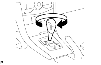
| 82. INSTALL SHIFT LEVER KNOB SUB-ASSEMBLY (for Automatic Transaxle) |
Turn the shift lever knob clockwise and install the shift lever knob sub-assembly.
 |
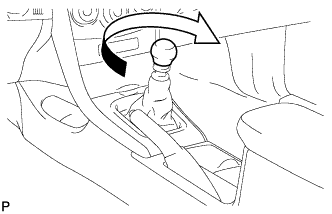
| 83. INSTALL SHIFT LEVER KNOB SUB-ASSEMBLY (for Manual Transaxle) |
Turn the shift lever knob clockwise and install the shift lever knob sub-assembly.
 |
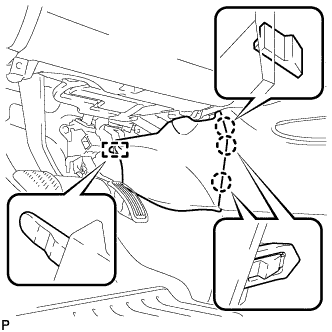
| 84. INSTALL LOWER INSTRUMENT PANEL FINISH PANEL LH |
Engage the 3 claws and clip, and then install the lower instrument panel finish panel LH.
 |
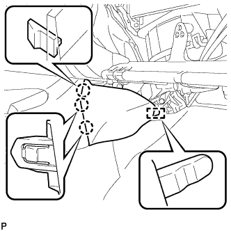
| 85. INSTALL LOWER INSTRUMENT PANEL FINISH PANEL RH |
Engage the 3 claws and clip, and then install the lower instrument panel finish panel RH.
 |
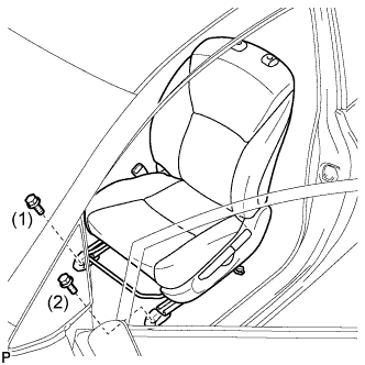
| 86. INSTALL FRONT SEAT ASSEMBLY LH (for Manual Seat) |
Place the front seat assembly in the cabin.
- NOTICE:
- Be careful not to damage the vehicle body.
Connect the connectors under the seat.
Temporarily install the front seat assembly with the 4 bolts.
Lift up the seat track adjusting handle and move the seat to the rearmost position.
Tighten the 2 bolts on the front side of the seat.
- Torque:
- 37 N*m{377 kgf*cm, 27 ft.*lbf}
- HINT:
- Tighten the bolts in the order indicated in the illustration.
 |
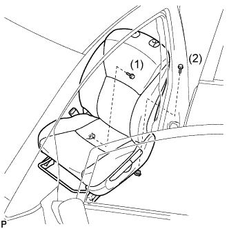
Lift up the seat track adjusting handle and move the seat to the foremost position.
Tighten the 2 bolts on the rear side of the seat.
- Torque:
- 37 N*m{377 kgf*cm, 27 ft.*lbf}
- HINT:
- Tighten the bolts in the order indicated in the illustration.
 |
| 87. INSPECT FRONT SEAT SLIDE ADJUSTER LOCK (for Manual Seat) |
While sliding the front seat, check that the left and right adjusters move together smoothly and lock simultaneously.
If the seat adjusters do not lock simultaneously, loosen the bolts securing the seat to adjust the adjuster position.
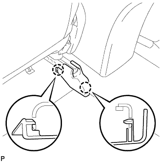
| 88. INSTALL INNER SEAT TRACK COVER LH (for Manual Seat) |
Lift up the seat track adjusting handle and move the seat to the rearmost position.
Engage the 2 claws and install the inner seat track cover.
 |
| 89. INSTALL OUTER SEAT TRACK COVER LH (for Manual Seat) |
Engage the 2 claws and install the outer seat track cover.
 |
| 90. INSTALL FRONT SEAT HEADREST ASSEMBLY (for Manual Seat) |
| 91. INSTALL FRONT SEAT ASSEMBLY LH (for Power Seat) |
Place the front seat assembly in the cabin.
- NOTICE:
- Be careful not to damage the vehicle body.
Connect the connectors under the seat.
Connect the cable to the negative (-) battery terminal.
Temporarily install the front seat assembly with the 4 bolts.
Operate the power seat switch knob and move the seat to the rearmost position.
Tighten the 2 bolts on the front side of the seat.
- Torque:
- 37 N*m{377 kgf*cm, 27 ft.*lbf}
- HINT:
- Tighten the bolts in the order indicated in the illustration.
 |
Operate the power seat switch knob and move the seat to the foremost position.
Tighten the 2 bolts on the rear side of the seat.
- Torque:
- 37 N*m{377 kgf*cm, 27 ft.*lbf}
- HINT:
- Tighten the bolts in the order indicated in the illustration.
 |
| 92. INSTALL INNER SEAT TRACK COVER LH (for Power Seat) |
Engage the 2 claws and install the inner seat track cover.
 |
| 93. INSTALL OUTER SEAT TRACK COVER LH (for Power Seat) |
Engage the 2 claws and install the outer seat track cover.
|
| 94. INSTALL FRONT SEAT HEADREST ASSEMBLY (for Power Seat) |
| 95. INSTALL FRONT SEAT ASSEMBLY RH (for Manual Seat) |
- HINT:
- Use the same procedure for the RH side and LH side (COROLLA_ZRE142 RM000000Z8T0D2X_01_0001.html).
| 96. INSPECT FRONT SEAT SLIDE ADJUSTER LOCK (for Manual Seat) |
While sliding the front seat, check that the left and right adjusters move together smoothly and lock simultaneously.
If the seat adjusters do not lock simultaneously, loosen the bolts securing the seat to adjust the adjuster position.
| 97. INSTALL INNER SEAT TRACK COVER RH (for Manual Seat) |
- HINT:
- Use the same procedure for the RH side and LH side (COROLLA_ZRE142 RM000000Z8T0D2X_01_0003.html).
| 98. INSTALL OUTER SEAT TRACK COVER RH (for Manual Seat) |
- HINT:
- Use the same procedure for the RH side and LH side (COROLLA_ZRE142 RM000000Z8T0D2X_01_0014.html).
| 99. INSTALL FRONT SEAT HEADREST ASSEMBLY (for Manual Seat) |
| 100. CONNECT CABLE TO NEGATIVE BATTERY TERMINAL (for Manual Seat) |
| 101. INSPECT SHIFT LEVER POSITION (for Automatic Transaxle) |
for U341E: (COROLLA_ZRE142 RM0000020U405KX_01_0001.html)
| 102. ADJUST SHIFT LEVER POSITION (for Automatic Transaxle) |
for U341E: (COROLLA_ZRE142 RM0000020U405KX_01_0002.html)
| 103. INSPECT SRS WARNING LIGHT |
| 104. INSPECT FRONT SEAT ASSEMBLY (for Power Seat) |
Inspect the power seat operation.