Drivetrain. Corolla. Zre142 Aze141
U250E Automatic Transmission Transaxle. Corolla. Zre142 Aze141
TYPICAL MALFUNCTION THRESHOLDS
CHECK OTHER DTCS OUTPUT (IN ADDITION TO DTC P2714)
INSPECT SHIFT SOLENOID VALVE SLT
INSPECT TRANSMISSION VALVE BODY ASSEMBLY
INSPECT TORQUE CONVERTER ASSEMBLY
DTC P2714 Pressure Control Solenoid "D" Performance (Shift Solenoid Valve SLT) |
SYSTEM DESCRIPTION
Shift solenoid valve SLT controls the transmission line pressure for smooth transmission operation based on signals from the throttle position sensor and vehicle speed sensor. The ECM adjusts the current to shift solenoid valve SLT to control the hydraulic line pressure coming from the primary regulator valve. Appropriate line pressure assures smooth shifting with varying engine outputs.
| DTC No. | DTC Detection Condition | Trouble Area |
| P2714 | ECM detects a malfunction on SLT (ON side) according to the revolution difference of the turbine, intermediate and the output shaft, and also by the oil pressure. (2-trip detection logic) |
|
MONITOR DESCRIPTION
In any forward position, when the difference in the revolutions of the turbine, intermediate and output shaft exceeds the specified value (varies with intermediate and output speed) determined by the ECM, the ECM illuminates the MIL and stores the DTC.When shift solenoid valve SLT remains on, the oil pressure goes down and the clutch engagement force decreases.
- NOTICE:
- If you continue driving under these conditions, the clutch will burn out and the vehicle will no longer be drivable.
MONITOR STRATEGY
| Related DTCs | P2714: Shift solenoid valve SLT/ON malfunction |
| Required sensors/Components | Shift solenoid valve SLT, Speed sensor (NT), Speed sensor (NC), Crankshaft position sensor (NE) |
| Frequency of operation | Continuous |
| Duration | 1 sec. |
| MIL operation | 2 driving cycles |
| Sequence of operation | None |
TYPICAL ENABLING CONDITIONS
| The monitor will run whenever this DTC is not present. (Not circuit malfunction) | P0712, P0713 (ATF temperature sensor circuit) P0717 (Turbine speed sensor circuit) P0793 (Intermediate shaft speed sensor circuit) P0500 (Vehicle speed sensor circuit) P0748 (Shift solenoid valve SL1 circuit) P0778 (Shift solenoid valve SL2 circuit) P0798 (Shift solenoid valve SL3 circuit) P0982, P0983 (Shift solenoid valve S4 circuit) P0985, P0986 (Shift solenoid valve SR circuit) P2769, P2770 (Shift solenoid valve DSL circuit) P2716 (Shift solenoid valve SLT circuit) P0120, P0121, P0122, P0123, P0220, P0222, P0223, P0604, P0606, P0607, P060A, P060D, P060E, P0657, P1607, P2102, P2103, P2111, P2112, P2118, P2119, P2135 (Electronic throttle system) |
| Transmission range | "D" |
| TFT (Transmission fluid temperature) | -20°C (-4°F) or more |
| ECM selected gear | 4th |
| Temporary MAIN gear | 1st or 2nd or 3rd or 4th |
| NT - NC x Temporary MAIN gear ratio NT: Input (turbine) speed NC: Intermediate shaft speed | More than 100 rpm at Intermediate shaft speed 1,000 rpm |
| Temporary U/D gear | Low or High |
| NC - NO x Temporary U/D gear ratio NO: Output speed | More than 300 rpm at Output speed 1,000 rpm |
| TT TT: Turbine Torque | 142 Nm or more |
| NT | 250 rpm or more |
| NC | 250 rpm or more |
| NO | 250 rpm or more |
| ECM selected gear | 5th |
| Temporary MAIN gear | 1st or 2nd or 3rd or 4th |
| NT - NC x Temporary MAIN gear ratio NT: Input (turbine) speed NC: Intermediate shaft speed | More than 100 rpm at Intermediate shaft speed 1,000 rpm |
| Temporary U/D gear | Low or High |
| NC - NO x Temporary U/D gear ratio NO: Output speed | More than 300 rpm at Output speed 1,000 rpm |
| TT TT: Turbine Torque | 142 Nm or more |
| NT | 250 rpm or more |
| NC | 250 rpm or more |
| NO | 250 rpm or more |
TYPICAL MALFUNCTION THRESHOLDS
[ON malfunction]Detection condition: Total accumulated time of ON malfunctions (a) and (b) is 1 second or more
| NT - NC x 4th gear ratio | More than 100 rpm at Intermediate shaft speed 1,000 rpm |
| NC - NO x Low gear ratio | More than 300 rpm at Output speed 1,000 rpm |
| Duration | 0.85 sec. or more |
| NT - NC x 4th gear ratio | More than 100 rpm at Intermediate shaft speed 1,000 rpm |
| NC - NO x High gear ratio | More than 300 rpm at Output speed 1,000 rpm |
| Duration | 0.85 sec. or more |
INSPECTION PROCEDURE
- NOTICE:
- Perform the universal trip to clear permanent DTCs (COROLLA_ZRE142 RM000000W770S6X.html).
| 1.CHECK OTHER DTCS OUTPUT (IN ADDITION TO DTC P2714) |
Connect Techstream to the DLC3.
Turn the ignition switch to the on position and turn the Techstream main switch ON.
When you use Techstream:
Select the item "Powertrain / Engine and ECT / Trouble Codes".
Read the DTCs using Techstream.
- Result:
Display (DTC output) Proceed to Only P2714 is output A P2714 and other DTCs B
- HINT:
- If any other codes besides "P2714" are output, perform troubleshooting for those DTCs first.
|
| ||||
| A | |
| 2.INSPECT SHIFT SOLENOID VALVE SLT |
Remove the shift solenoid valve SLT.
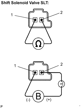 |
Measure the resistance according to the value(s) in the table below.
- Standard resistance:
Tester Connection Condition Specified Condition 1 - 2 20°C (68°F) 5.0 to 5.6 Ω
Connect the positive (+) lead with a 21 W bulb to terminal 2 and the negative (-) lead to terminal 1 of the solenoid valve connector, then check the movement of the valve.
- OK:
- The solenoid makes an operating sound.
|
| ||||
| OK | |
| 3.INSPECT TRANSMISSION VALVE BODY ASSEMBLY |
- OK:
- There are no foreign objects on each valve.
|
| ||||
| OK | |
| 4.INSPECT TORQUE CONVERTER ASSEMBLY |
- OK:
- The torque converter assembly operates normally.
|
| ||||
| OK | ||
| ||