Vehicle Interior. Corolla. Zre142 Aze141
Lighting (Int). Corolla. Zre142 Aze141
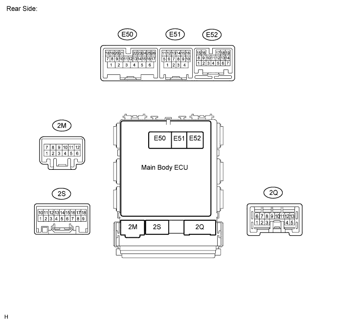
Lighting System -- Terminals Of Ecu |
| CHECK MAIN BODY ECU (w/o Smart Key System) |
Disconnect the 2B, 2E, 2F, and 2G instrument junction block connectors.


Measure the voltage and resistance between the wire harness side connectors and body ground.
- Standard Voltage:
Terminal No. (Symbol) Wiring Color Terminal Description Condition Specified Condition 2B-30 (BECU) - Body ground W - Body ground Battery power supply Always 11 to 14 V 2F-5 (ACC) - Body ground W*1 - Body ground
L*2 - Body groundACC power supply Always 11 to 14 V 2G-1 - Body ground W - Body ground Battery power supply Always 11 to 14 V
- Standard Resistance:
Terminal No. (Symbol) Wiring Color Terminal Description Condition Specified Condition 2E-17 (GND1) - Body ground W-B - Body ground Ground Always Below 1 Ω
- HINT:
- *1: for TMC Made
- *2: except TMC Made
Reconnect the 2B, 2E, 2F and 2G instrument panel junction block connectors.
Measure the voltage according to the value(s) in the table below.
- Standard Voltage:
Terminal No. (Symbol) Wiring Color Terminal Description Condition Specified Condition 2A-7 (LGCY) - Body ground LG - Body ground Luggage compartment door courtesy switch input Luggage compartment door open Below 1 V Luggage compartment door closed 11 to 14 V 2A-21 (DCTY) - Body ground W*1 - Body ground
V*2 - Body groundDriver side door courtesy switch input Driver side door open Below 1 V Driver side door closed Pulse generation 2C-6 (DCTY) - Body ground BR*1 - Body ground
R*2 - Body groundDriver side door courtesy switch input Driver side door open Below 1 V Driver side door closed Pulse generation 2E-19 (RCTY) - Body ground LG*1 - Body ground
Y*2 - Body groundRear door courtesy switch RH input Rear door RH open Below 1 V Rear door RH closed Pulse generation 2E-20 (PCTY) - Body ground BR*1 - Body ground
BE*2 - Body groundFront passenger side door courtesy switch input Front passenger side door open Below 1 V Front passenger side door closed Pulse generation 2K-2 (ILE) - Body ground W*1 - Body ground
GR*2 - Body groundInterior light drive output Interior light switch in DOOR position and interior light ON Below 1 V Interior light switch in DOOR position and interior light OFF 11 to 14 V E61-5 (LSWP) - Body ground B*1 - Body ground
R*2 - Body groundFront passenger side door lock position switch input Front passenger door unlocked Below 1 V Front passenger door locked Pulse generation E61-13 (LCTY) - Body ground SB*1 - Body ground
B*2 - Body groundRear door courtesy switch LH input Rear door LH open Below 1 V Rear door LH closed Pulse generation E61-21 (LSWD) - Body ground Y - Body ground Driver side door lock position switch input Driver side door unlocked Below 1 V Driver side door locked Pulse generation
- *1: for TMC Made
- *2: except TMC Made
| CHECK MAIN BODY ECU (w/ Smart Key System) |
Disconnect the 2B, 2E, 2F, and 2G instrument junction block connectors.
Measure the voltage and resistance between the wire harness side connectors and body ground.
- Standard Voltage:
Terminal No. (Symbol) Wiring Color Terminal Description Condition Specified Condition 2F-5 (ACC) - Body ground L - Body ground ACC power supply Always 11 to 14 V 2G-1 - Body ground W - Body ground Battery power supply Always 11 to 14 V
- Standard Resistance:
Terminal No. (Symbol) Wiring Color Terminal Description Condition Specified Condition 2E-17 (GND1) - Body ground W-B - Body ground Ground Always Below 1 Ω
Reconnect the 2B, 2E, 2F, 2G and E51 instrument panel junction block connectors.
Measure the voltage according to the value(s) in the table below.
- Standard Voltage:
Terminal No. (Symbol) Wiring Color Terminal Description Condition Specified Condition 2A-7 (LGCY) - Body ground LG - Body ground Luggage compartment door courtesy switch input Luggage compartment door open Below 1 V Luggage compartment door closed Pulse generation 2A-21 (DCTY) - Body ground V - Body ground Driver side door courtesy switch input Driver side door open Below 1 V Driver side door closed Pulse generation 2E-19 (RCTY) - Body ground Y - Body ground Rear door courtesy switch RH input Rear door RH open Below 1 V Rear door RH closed Pulse generation 2E-20 (PCTY) - Body ground BE - Body ground Front passenger side door courtesy switch input Passenger side door open Below 1 V Passenger side door closed Pulse generation 2K-2 (ILE) - Body ground GR - Body ground Interior light driver output Interior light switch in DOOR position and interior light ON Below 1 V Interior light switch in DOOR position and interior light OFF 11 to 14 V E50-8 (LCTY) - Body ground B - Body ground Rear left door courtesy switch input Rear door LH open Below 1 V Rear door RH closed Pulse generation E50-10 (LSWP) - Body ground R - Body ground Front passenger side door lock position switch input Front passenger door unlocked Below 1 V Front passenger door locked Pulse generation E50-25 (LSWD) - Body ground Y - Body ground Driver side door lock position switch input Driver side door locked Pulse generation Driver side door unlocked Below 1 V E52-10 (LSR) - Body ground G - Body ground Rear door lock position switch input Rear door LH or RH unlocked Below 1 V Rear door LH and RH locked Pulse generation