Steering Gear -- Removal |
| 1. PLACE FRONT WHEELS FACING STRAIGHT AHEAD |
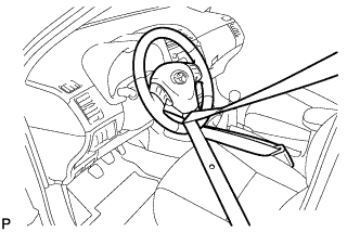
| 2. SECURE STEERING WHEEL |
Secure the steering wheel with the seat belt in order to prevent rotation.
- HINT:
- This operation is useful to prevent damage to the spiral cable.
 |
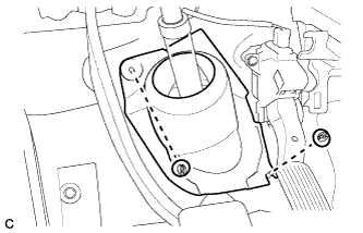
| 3. REMOVE COLUMN HOLE COVER SILENCER SHEET |
Turn back the floor carpet, and remove the 2 clips and column hole cover silencer sheet.
 |
| 4. SEPARATE NO. 2 STEERING INTERMEDIATE SHAFT ASSEMBLY |
Put matchmarks on the No. 2 steering intermediate shaft assembly and the steering intermediate shaft.
 |
Remove the bolt and separate the No. 2 steering intermediate shaft assembly from the steering intermediate shaft.
| 5. SEPARATE NO. 1 STEERING COLUMN HOLE COVER SUB-ASSEMBLY |
Remove clips A and the No. 1 steering column hole cover sub-assembly and disengage clip B from the body.
- NOTICE:
- Do not damage clips A and B.
 |
| 6. REMOVE FRONT WHEELS |
| 7. REMOVE ENGINE UNDER COVER LH |
| 8. REMOVE ENGINE UNDER COVER RH |
| 9. SEPARATE TIE ROD END SUB-ASSEMBLY LH |
Remove the cotter pin and the nut.
Install SST to the tie rod end.
- SST
- 09960-20010(09961-02060)
- NOTICE:
- Make sure that the upper ends of the tie rod end and SST are aligned.
 |
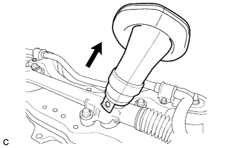
Using SST, separate the tie rod end from the steering knuckle.

- SST
- 09960-20010(09961-02010)
- CAUTION:
- Apply grease to the threads of the bolt and the tip of SST.
- NOTICE:
- Be sure to tighten the string firmly to secure SST to the steering knuckle to prevent SST from falling off.
- Install SST with the center nut so that A and B are parallel. Otherwise, the dust cover may be damaged.
- Be sure to place the wrench on the part indicated in the illustration.
- Do not damage the front disc brake dust cover.
- Do not damage the ball joint dust cover.
- Do not damage the steering knuckle.
| 10. SEPARATE TIE ROD END SUB-ASSEMBLY RH |
- HINT:
- Perform the same procedure as for the LH side.
| 11. SEPARATE FRONT STABILIZER LINK ASSEMBLY LH |
Remove the nut and separate the stabilizer link assembly from the front shock absorber with coil spring.
- NOTICE:
- If the ball joint turns together with the nut, use a hexagon wrench (6 mm) to hold the stud bolt.
 |
| 12. SEPARATE FRONT STABILIZER LINK ASSEMBLY RH |
- HINT:
- Perform the same procedure as for the LH side.
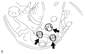
| 13. SEPARATE FRONT LOWER SUSPENSION ARM LH |
Remove the bolt and 2 nuts, and separate the front lower suspension arm from the lower ball joint.
 |
| 14. SEPARATE FRONT LOWER SUSPENSION ARM RH |
- HINT:
- Perform the same procedure as for the LH side.
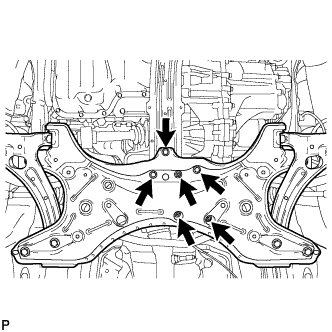
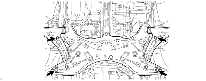
| 15. REMOVE FRONT SUSPENSION CROSSMEMBER SUB-ASSEMBLY |
Remove the 3 bolts and 3 nuts.
 |
Using a transmission jack or equivalent, support the front suspension crossmember sub-assembly.
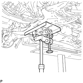 |
Remove the 4 bolts and front suspension crossmember sub-assembly.
| 16. REMOVE NO. 1 STEERING COLUMN HOLE COVER SUB-ASSEMBLY |
Remove the No. 1 steering column hole cover sub-assembly from the steering link assembly.
 |
| 17. REMOVE STEERING INTERMEDIATE SHAFT |
Put matchmarks on the steering intermediate shaft and the steering link assembly.
 |
Remove the bolt and the steering intermediate shaft from the steering link assembly.
| 18. REMOVE STEERING LINK ASSEMBLY |
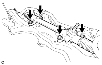
Remove the 4 bolts and steering link assembly from the front suspension crossmember sub-assembly.
 |
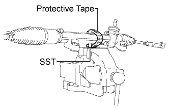
| 19. SECURE STEERING LINK ASSEMBLY |
Using SST, secure the steering link assembly in a vise.
- SST
- 09612-00012
- HINT:
- Tape SST before use.
 |
| 20. REMOVE TIE ROD END SUB-ASSEMBLY LH |
 |
Put matchmarks on the tie rod end sub-assembly LH and steering gear assembly.
Remove the tie rod end sub-assembly LH and lock nut.
| 21. REMOVE TIE ROD END SUB-ASSEMBLY RH |
- HINT:
- Perform the same procedure as for the LH side.