DESCRIPTION
WIRING DIAGRAM
INSPECTION PROCEDURE
CHECK REAR WINDOW DEFOGGER SYSTEM
CHECK HARNESS AND CONNECTOR (REAR WINDOW DEFOGGER WIRE - INSTRUMENT PANEL JUNCTION BLOCK)
CHECK HARNESS AND CONNECTOR (REAR WINDOW DEFOGGER WIRE - BATTERY)
CHECK HARNESS AND CONNECTOR (REAR WINDOW DEFOGGER WIRE - BODY GROUND)
INSPECT FUSES (DEF, ECU-IG NO. 2, HTR-IG)
CHECK HARNESS AND CONNECTOR (IG1 RELAY POWER SOURCE)
CHECK HARNESS AND CONNECTOR (INSTRUMENT PANEL JUNCTION BLOCK - BATTERY)
CHECK HARNESS AND CONNECTOR (HEATER CONTROL (BLOWER SWITCH) - INSTRUMENT PANEL J/B)
CHECK HARNESS AND CONNECTOR (HEATER CONTROL (BLOWER SWITCH) - BATTERY)
CHECK HARNESS AND CONNECTOR (HEATER CONTROL (BLOWER SWITCH) - BODY GROUND)
WINDOW DEFOGGER SYSTEM (for Manual Air Conditioning System) - Rear Window Defogger System does not Operate |
DESCRIPTION
When the rear window defogger switch, which is built into the heater control (blower switch), is operated, the operation signals are transmitted to the DEF relay (coil side). When the DEF relay (coil side) receives the signals, it turns on the DEF relay (switch side) to operate the rear window defogger.
WIRING DIAGRAM
INSPECTION PROCEDURE
| 1.CHECK REAR WINDOW DEFOGGER SYSTEM |
Turn the window defogger switch on.
Check that operation sound of the DEF relay is heard.
- OK:
- Relay operating sound is heard
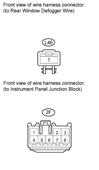
| 2.CHECK HARNESS AND CONNECTOR (REAR WINDOW DEFOGGER WIRE - INSTRUMENT PANEL JUNCTION BLOCK) |
Disconnect the 2F instrument panel junction block and L46 rear window defogger wire connectors.
Measure the resistance according to the value(s) in the table below.
- Standard Resistance:
Tester Connection
| Condition
| Specified Condition
|
L46-1 - 2F-2
| Always
| Below 1 Ω
|
L46-1 - Body ground
| Always
| 10 kΩ or higher
|
| | REPAIR OR REPLACE HARNESS OR CONNECTOR |
|
|
| 3.CHECK HARNESS AND CONNECTOR (REAR WINDOW DEFOGGER WIRE - BATTERY) |
Reconnect the 2F instrument panel junction block connector.
Measure the voltage according to the value(s) in the table below.
- Standard Voltage:
Tester Connection
| Condition
| Specified Condition
|
L46-1 - Body ground
| Ignition switch ON, Rear window defogger switch ON
| 11 to 14 V
|
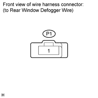
| 4.CHECK HARNESS AND CONNECTOR (REAR WINDOW DEFOGGER WIRE - BODY GROUND) |
Disconnect the P1 rear window defogger wire connector.
Measure the resistance according to the value(s) in the table below.
- Standard Resistance:
Tester Connection
| Condition
| Specified Condition
|
P1-1 - Body ground
| Always
| Below 1 Ω
|
| | REPAIR OR REPLACE HARNESS OR CONNECTOR |
|
|
| 5.INSPECT FUSES (DEF, ECU-IG NO. 2, HTR-IG) |
Remove the DEF, ECU-IG No. 2 and HTR-IG fuses from the instrument panel junction block.
Measure the resistance according to the value(s) in the table below.
- Standard Resistance:
Item
| Condition
| Specified Condition
|
DEF fuse
| Always
| Below 1 Ω
|
ECU-IG No. 2 fuse
| Always
| Below 1 Ω
|
HTR-IG fuse
| Always
| Below 1 Ω
|
| 6.CHECK HARNESS AND CONNECTOR (IG1 RELAY POWER SOURCE) |
Disconnect the 2F instrument panel junction block connector.
Measure the voltage according to the value(s) in the table below.
- Standard Voltage:
Tester Connection
| Condition
| Specified Condition
|
2F-3 - Body Ground
| Ignition switch ON
| 11 to 14 V
|
- Result:
Result
| Proceed to
|
OK
| A
|
NG (w/ Smart Key System)
| B
|
NG (w/o Smart Key System)
| C
|
| |
|
| | REPAIR OR REPLACE HARNESS OR CONNECTOR |
|
|
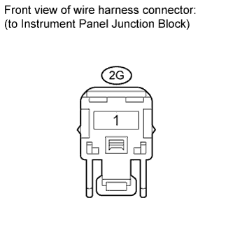
| 7.CHECK HARNESS AND CONNECTOR (INSTRUMENT PANEL JUNCTION BLOCK - BATTERY) |
Disconnect the 2G instrument panel junction block connector.
Measure the voltage according to the value(s) in the table below.
- Standard Voltage:
Tester Connection
| Condition
| Specified Condition
|
2G-1 - Body ground
| Ignition switch ON
| 11 to 14 V
|
| | REPAIR OR REPLACE HARNESS OR CONNECTOR |
|
|
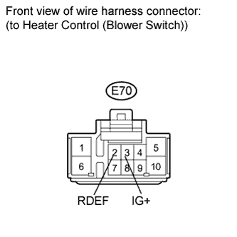
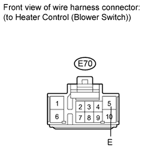
| 8.CHECK HARNESS AND CONNECTOR (HEATER CONTROL (BLOWER SWITCH) - INSTRUMENT PANEL J/B) |
Disconnect the E70 heater control (blower switch) and 2Q instrument panel junction block connectors.
Measure the resistance according to the value(s) in the table below.
- Standard Resistance:
Tester Connection
| Condition
| Specified Condition
|
E70-2 (RDEF) - 2Q-12
| Always
| Below 1 Ω
|
E70-3 (IG+) - 2Q-10
| Always
| Below 1 Ω
|
E70-2 (RDEF) - Body ground
| Always
| 10 kΩ or higher
|
E70-3 (IG+) - Body ground
| Always
| 10 kΩ or higher
|
| | REPAIR OR REPLACE HARNESS OR CONNECTOR |
|
|
| 9.CHECK HARNESS AND CONNECTOR (HEATER CONTROL (BLOWER SWITCH) - BATTERY) |
Reconnect the 2Q instrument panel junction block connector.
Measure the voltage according to the value(s) in the table below.
- Standard Voltage:
Tester Connection
| Condition
| Specified Condition
|
E70-2 (RDEF) - Body ground
| Ignition switch ON
| 11 to 14 V
|
E70-3 (IG+) - Body ground
| Ignition switch ON
| 11 to 14 V
|
| 10.CHECK HARNESS AND CONNECTOR (HEATER CONTROL (BLOWER SWITCH) - BODY GROUND) |
Measure the resistance according to the value(s) in the table below.
- Standard Resistance:
Tester Connection
| Condition
| Specified Condition
|
E70-5 (E) - Body ground
| Always
| Below 1 Ω
|
| | REPAIR OR REPLACE HARNESS OR CONNECTOR |
|
|