Rear Axle Hub On-Vehicle Inspection
REMOVE REAR WHEEL
REMOVE LOWER INSTRUMENT PANEL FINISH PANEL LH (for Rear Disc Brake)
REMOVE LOWER INSTRUMENT PANEL FINISH PANEL RH (for Rear Disc Brake)
REMOVE SHIFT LEVER KNOB SUB-ASSEMBLY (for Rear Disc Brake)
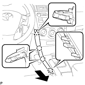
REMOVE CENTER INSTRUMENT CLUSTER FINISH PANEL ASSEMBLY (for Rear Disc Brake)
REMOVE UPPER CONSOLE PANEL SUB-ASSEMBLY (for Rear Disc Brake)
LOOSEN PARKING BRAKE CABLE (for Rear Disc Brake)
REMOVE PARKING BRAKE LEVER PROTECTOR (for Rear Disc Brake)
SEPARATE NO. 3 PARKING BRAKE CABLE ASSEMBLY (for Rear Disc Brake)
SEPARATE REAR DISC BRAKE CALIPER ASSEMBLY (for Rear Disc Brake)
REMOVE REAR DISC (for Rear Disc Brake)
REMOVE REAR BRAKE DRUM (for Rear Drum Brake)
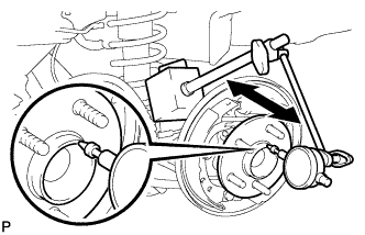
INSPECT REAR AXLE HUB BEARING LOOSENESS (for Rear Drum Brake)
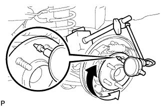
INSPECT REAR AXLE HUB RUNOUT (for Rear Drum Brake)
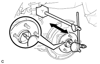
INSPECT REAR AXLE HUB BEARING LOOSENESS (for Rear Disc Brake)
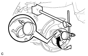
INSPECT REAR AXLE HUB RUNOUT (for Rear Disc Brake)
INSTALL REAR BRAKE DRUM (for Rear Drum Brake)
ADJUST REAR DRUM BRAKE SHOE CLEARANCE (for Rear Drum Brake)
INSTALL REAR DISC (for Rear Disc Brake)
INSTALL REAR DISC BRAKE CALIPER ASSEMBLY (for Rear Disc Brake)
CONNECT NO. 3 PARKING BRAKE CABLE ASSEMBLY (for Rear Disc Brake)
ADJUST PARKING BRAKE LEVER TRAVEL (for Rear Disc Brake)
INSTALL PARKING BRAKE LEVER PROTECTOR
INSPECT REAR DISC BRAKE CYLINDER OPERATION LEVER AND STOPPER CLEARANCE (for Rear Disc Brake)
INSTALL UPPER CONSOLE PANEL SUB-ASSEMBLY (for Rear Disc Brake)
INSTALL CENTER INSTRUMENT CLUSTER FINISH PANEL ASSEMBLY (for Rear Disc Brake)
INSTALL SHIFT LEVER KNOB SUB-ASSEMBLY (for Rear Disc Brake)
INSTALL LOWER INSTRUMENT PANEL FINISH PANEL LH (for Rear Disc Brake)
INSTALL LOWER INSTRUMENT PANEL FINISH PANEL RH (for Rear Disc Brake)
INSTALL REAR WHEEL
Rear Axle Hub -- On-Vehicle Inspection |
- HINT:
- Use the same procedure for the RH side and LH side.
- The procedure listed below is for the LH side.
| 2. REMOVE LOWER INSTRUMENT PANEL FINISH PANEL LH (for Rear Disc Brake) |
Disengage the 3 claws and clip, and then remove the lower instrument panel finish panel LH.
| 3. REMOVE LOWER INSTRUMENT PANEL FINISH PANEL RH (for Rear Disc Brake) |
Disengage the 3 claws and clip, and then remove the lower instrument panel finish panel RH.
| 4. REMOVE SHIFT LEVER KNOB SUB-ASSEMBLY (for Rear Disc Brake) |
- HINT:
- for Manual Transaxle (COROLLA_ZRE142 RM000002XV501QX_01_0022.html)
- for Automatic Transaxle (COROLLA_ZRE142 RM000002XV501QX_01_0025.html)
| 5. REMOVE CENTER INSTRUMENT CLUSTER FINISH PANEL ASSEMBLY (for Rear Disc Brake) |
- HINT:
- for Manual Transaxle (COROLLA_ZRE142 RM000002XV501QX_01_0017.html)
- for Automatic Transaxle (COROLLA_ZRE142 RM000002XV501QX_01_0028.html)
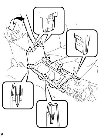
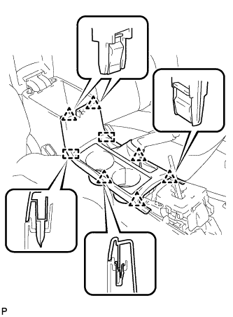
| 6. REMOVE UPPER CONSOLE PANEL SUB-ASSEMBLY (for Rear Disc Brake) |
Using a moulding remover, disengage the 6 clips and 2 guides, and remove the upper console panel sub-assembly.
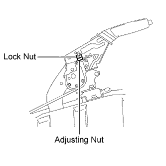
| 7. LOOSEN PARKING BRAKE CABLE (for Rear Disc Brake) |
Loosen the lock nut and adjusting nu to completely release the parking brake cable.
| 8. REMOVE PARKING BRAKE LEVER PROTECTOR (for Rear Disc Brake) |
Remove the parking brake lever protector from the No. 3 parking brake cable assembly.
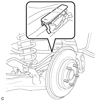
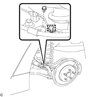
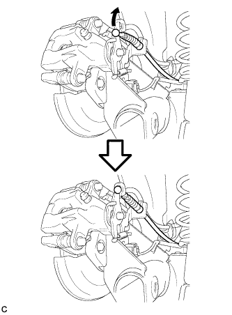
| 9. SEPARATE NO. 3 PARKING BRAKE CABLE ASSEMBLY (for Rear Disc Brake) |
Disengage the clamp from the No. 3 parking brake cable assembly.
Remove the bolt.
Separate the No. 3 parking brake cable assembly from the rear disc brake cylinder assembly.
Separate the No. 3 parking brake cable assembly from the rear disc brake cylinder assembly.
- HINT:
- Insert an offset wrench (14 mm) at the base of the No. 3 parking brake cable assembly as shown in the illustration to disengage the clip. Pull out the No. 3 parking brake cable assembly from the rear disc brake cylinder assembly.
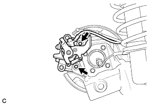
| 10. SEPARATE REAR DISC BRAKE CALIPER ASSEMBLY (for Rear Disc Brake) |
Remove the 2 bolts, and separate the rear disc brake caliper assembly.
- NOTICE:
- Use wire or an equivalent tool to keep the brake caliper from hanging down by the flexible hose.
| 11. REMOVE REAR DISC (for Rear Disc Brake) |
Remove the rear disc.
- HINT:
- Place matchmarks on the disc and axle hub.
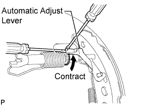
| 12. REMOVE REAR BRAKE DRUM (for Rear Drum Brake) |
Release the parking brake and remove the rear brake drum.
- HINT:
- If the rear brake drum cannot be removed easily, perform the following procedure.
Remove the shoe adjusting hole plug and insert a screwdriver through the hole into the backing plate, and hold the automatic adjust lever away from the adjuster.
Using another screwdriver, contract the brake shoe by turning the adjusting bolt.
| 13. INSPECT REAR AXLE HUB BEARING LOOSENESS (for Rear Drum Brake) |
Using a dial indicator, check for looseness near the center of the axle hub.
- Maximum looseness:
- 0.05 mm (0.00196 in.)
- NOTICE:
- Ensure that the dial indicator is set perpendicular to the measurement surface.
If the looseness exceeds the maximum, replace the rear axle hub and bearing assembly.
| 14. INSPECT REAR AXLE HUB RUNOUT (for Rear Drum Brake) |
Using a dial indicator, check for runout on the surface of the axle hub outside the hub bolt.
- Maximum runout:
- 0.06 mm (0.00236 in.)
- NOTICE:
- Ensure that the dial indicator is set perpendicular to the measurement surface.
If the runout exceeds the maximum, replace the rear axle hub and bearing assembly.
| 15. INSPECT REAR AXLE HUB BEARING LOOSENESS (for Rear Disc Brake) |
Using a dial indicator, check for looseness near the center of the axle hub.
- Maximum looseness:
- 0.05 mm (0.00196 in.)
- NOTICE:
- Ensure that the dial indicator is set perpendicular to the measurement surface.
If the looseness exceeds the maximum, replace the rear axle hub and bearing assembly.
| 16. INSPECT REAR AXLE HUB RUNOUT (for Rear Disc Brake) |
Using a dial indicator, check for runout on the surface of the axle hub outside the hub bolt.
- Maximum runout:
- 0.06 mm (0.00236 in.)
- NOTICE:
- Ensure that the dial indicator is set perpendicular to the measurement surface.
If the runout exceeds the maximum, replace the rear axle hub and bearing assembly.
| 17. INSTALL REAR BRAKE DRUM (for Rear Drum Brake) |
Install the rear brake drum.
| 18. ADJUST REAR DRUM BRAKE SHOE CLEARANCE (for Rear Drum Brake) |
Temporarily install the 2 wheel nuts.
Remove the shoe adjusting hole plug, and turn the adjuster to expand the shoe until the drum locks.
Hold the automatic adjust lever away from the adjuster, and contract the brake shoe by turning the adjust bolt using another screwdriver until the drum can rotate smoothly.
- Standard:
- 11 notches
Install the hole plug.
| 19. INSTALL REAR DISC (for Rear Disc Brake) |
Align the matchmarks of the disc and axle hub and install the disc.
- NOTICE:
- When replacing the disc with a new one, select the installation position where the rear disc has minimal runout.
| 20. INSTALL REAR DISC BRAKE CALIPER ASSEMBLY (for Rear Disc Brake) |
Install the rear disc brake caliper assembly with the 2 bolts.
- Torque:
- 63 N*m{642 kgf*cm, 46 ft.*lbf}
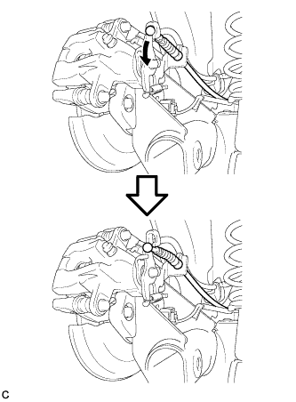
| 21. CONNECT NO. 3 PARKING BRAKE CABLE ASSEMBLY (for Rear Disc Brake) |
Install the No. 3 parking brake cable assembly to the rear disc brake cylinder assembly LH.
- HINT:
- Be sure to engage the No. 3 parking brake cable assembly clip onto the rear disc brake cylinder assembly LH as shown in the illustration.
Connect the No. 3 parking brake cable assembly to the rear disc brake cylinder assembly LH.
Install the bolt.
- Torque:
- 6.0 N*m{61 kgf*cm, 53 in.*lbf}
Engage the clamp to the No. 3 parking brake cable assembly.
| 22. ADJUST PARKING BRAKE LEVER TRAVEL (for Rear Disc Brake) |
Remove the upper console box assembly (COROLLA_ZRE142 RM000002XV501QX.html).
Completely release the parking brake lever.
Loosen the lock nut and the adjusting nut to completely release the parking brake cable.
Fully depress the brake lever 3 to 5 times with the engine stopped.
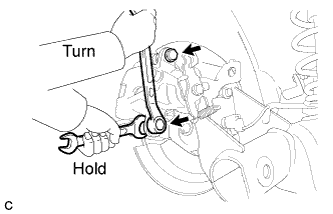
Turn the adjusting nut until the parking brake lever travel is corrected to within the specified range.
- Parking brake lever travel:
- 6 to 9 notches at 200 N (20 kgf, 45.0 lbf)
Using a wrench or an equivalent tool, hold the adjusting nut and tighten the lock nut.
- Torque:
- 6.0 N*m{61 kgf*cm, 53 in.*lbf}
Operate the parking brake lever 3 to 4 times, and check the parking brake lever travel.
Check whether the parking brake drags or not.
Install the upper console box assembly (COROLLA_ZRE142 RM000002XV301QX.html).
| 23. INSTALL PARKING BRAKE LEVER PROTECTOR |
Install the parking brake lever protector to the No. 3 parking brake cable assembly.
| 24. INSPECT REAR DISC BRAKE CYLINDER OPERATION LEVER AND STOPPER CLEARANCE (for Rear Disc Brake) |
To compensate for pad lining thickness, use SST to adjust the protrusion of the rear disc brake piston by turning it.
- SST
- 09719-12010(09719-01030)
- NOTICE:
- Place the disc between the 2 brake pads and determine the piston return value.
- Turn the rear disc brake piston to the position where the protrusion on the rear disc brake pad lines up properly with the piston groove.
Hold the rear disc brake cylinder slide pin, and install the rear disc brake cylinder assembly to the rear disc brake cylinder mounting with the 2 bolts.
- Torque:
- 35 N*m{357 kgf*cm, 26 ft.*lbf}
| 25. INSTALL UPPER CONSOLE PANEL SUB-ASSEMBLY (for Rear Disc Brake) |
Engage the 6 clips and 2 guides to install the upper console panel sub-assembly.
| 26. INSTALL CENTER INSTRUMENT CLUSTER FINISH PANEL ASSEMBLY (for Rear Disc Brake) |
- HINT:
- for Manual Transaxle (COROLLA_ZRE142 RM000002XV301QX_01_0024.html)
- for Automatic Transaxle (COROLLA_ZRE142 RM000002XV301QX_01_0016.html)
| 27. INSTALL SHIFT LEVER KNOB SUB-ASSEMBLY (for Rear Disc Brake) |
- HINT:
- for Manual Transaxle (COROLLA_ZRE142 RM000002XV301QX_01_0025.html)
- for Automatic Transaxle (COROLLA_ZRE142 RM000002XV301QX_01_0018.html)
| 28. INSTALL LOWER INSTRUMENT PANEL FINISH PANEL LH (for Rear Disc Brake) |
Disengage the 3 claws and clip, and then remove the lower instrument panel finish panel LH.
| 29. INSTALL LOWER INSTRUMENT PANEL FINISH PANEL RH (for Rear Disc Brake) |
Engage the 3 claws and clip, and then install the lower instrument panel finish panel RH.
- Torque:
- 103 N*m{1050 kgf*cm, 76 ft.*lbf}