Sliding Roof System Sliding Roof Ecu Power Source Circuit
DESCRIPTION
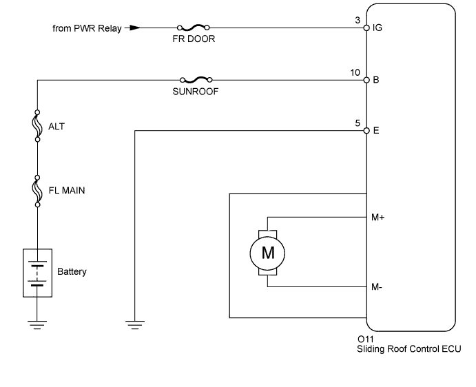
WIRING DIAGRAM
INSPECTION PROCEDURE
INSPECT FUSE (SUNROOF, FR DOOR)
CHECK HARNESS AND CONNECTOR (SLIDING ROOF DRIVE GEAR - BATTERY, BODY GROUND)
SLIDING ROOF SYSTEM - Sliding Roof ECU Power Source Circuit |
DESCRIPTION
If either the sliding function or tilt function does not operate, there may be a malfunction in the sliding roof control ECU power source circuit.
WIRING DIAGRAM
INSPECTION PROCEDURE
| 1.INSPECT FUSE (SUNROOF, FR DOOR) |
Remove the SUNROOF and FR DOOR fuses from the instrument panel junction block.
Measure the resistance according to the value(s) in the table below.
- Standard Resistance:
Tester Connection
| Condition
| Specified Condition
|
SUNROOF fuse
| Always
| Below 1 Ω
|
FR DOOR fuse
| Always
| Below 1 Ω
|
| 2.CHECK HARNESS AND CONNECTOR (SLIDING ROOF DRIVE GEAR - BATTERY, BODY GROUND) |
Disconnect the O11 ECU connector.
Measure the voltage and resistance according to the value(s) in the table below.
- Standard Voltage:
Tester Connection
| Condition
| Specified Condition
|
O11-10 (B) - Body ground
| Always
| 11 to 14 V
|
O11-3 (IG) - Body ground
| Ignition switch off
| Below 1 V
|
O11-3 (IG) - Body ground
| Ignition switch ON
| 11 to 14 V
|
- Standard Resistance:
Tester Connection
| Condition
| Specified Condition
|
O11-5 (E) - Body ground
| Always
| Below 1 Ω
|
| | REPAIR OR REPLACE HARNESS OR CONNECTOR |
|
|