Vehicle Interior. Corolla. Zre142 Aze141
Theft Deterrent Keyless Entry. Corolla. Zre142 Aze141
Theft Deterrent System -- Terminals Of Ecu |
| CHECK MAIN BODY ECU (INSTRUMENT PANEL JUNCTION BLOCK) |
Disconnect the 2A, 2B, 2E, 2F, 2G and E61 junction block connectors and main body ECU connectors.

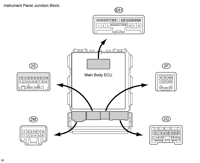
Measure the resistance and voltage between each terminal of the wire harness side connectors and body ground.
Tester Connection Wiring Color Terminal Description Condition Specified Condition 2A-7 (LGCY) - Body ground LG - Body ground Luggage compartment door courtesy light switch input Luggage compartment door CLOSED (OFF) → OPEN (ON) 10 kΩ or higher → Below 1 Ω 2A-21 (DCTY) - Body ground V - Body ground Driver side door courtesy light switch input Driver side door CLOSED (OFF) → OPEN (ON) 10 kΩ or higher → Below 1 Ω 2B-30 (BECU) - Body ground W - Body ground +B power supply Always 11 to 14 V 2E-19 (RCTY) - Body ground Y - Body ground Rear courtesy light switch RH input Rear door RH CLOSED (OFF) → OPEN (ON) 10 kΩ or higher → Below 1 Ω 2E-20 (PCTY) - Body ground BR - Body ground Passenger side courtesy light switch input Passenger side door CLOSED (OFF) → OPEN (ON) 10 kΩ or higher → Below 1 Ω 2F-5 (ACC) - Body ground L - Body ground Ignition power supply (ACC signal) Ignition switch ACC → off 11 to 14 V → Below 1 V 2G-1 (IG) - Body ground W - Body ground Ignition power supply (IG signal) Ignition switch ON → off 11 to 14 V → Below 1 V 2E-17 (GND1) - Body ground W-B - Body ground Ground Always Below 1 Ω E61-13 (LCTY) -Body ground B - Body ground Rear courtesy light switch LH input Rear door LH CLOSED (OFF) → OPEN (ON) 10 kΩ or higher → Below 1 Ω - HINT:
- If the result is not as specified, there may be a malfunction on the wire harness side.
| CHECK THEFT WARNING ECU ASSEMBLY |
Disconnect the E110 theft warning ECU assembly connector.

Measure the voltage and resistance between each terminal of the wire harness side connectors and body ground.
If the result is not as specified, there may be a malfunction on the wire harness side.Tester Connection Wiring Color Terminal Description Condition Specified Condition E110-7 (KSW) - E110-16 (E) L - W-B Unlock warning switch input No key in ignition key cylinder (OFF) → Key inserted (ON) 10 kΩ or higher → Below 1 Ω E110-9 (IG) - E110-16 (E) L -W-B Ignition power supply (IG signal) Ignition switch ON → off 11 to 14 V → Below 1 V E110-11 (+B1) - E110-16 (E) R - W-B +B power supply Always 11 to 14 V E110-16 (E) - Body ground W-B - Body ground Ground Always Below 1 Ω Reconnect the E110 theft warning ECU assembly connector.
Measure the voltage between each terminal of the connector.
Tester Connection Wiring Color Terminal Description Condition Specified Condition E110-24 (BRK+) - E110-16 (E) LG - W-B Alarm BERKES communication Theft deterrent system is in alarm sounding state Pulse generation
(1.5 V ← → Below 1.2 V)E110-25 (BRK-) - E110-16 (E) W - W-B Alarm BERKES communication All doors are locked using key (Theft deterrent system is in arming preparation state.) Pulse generation
(1.5 V ← → Below 1.2 V)E110-29 (IND) - E110-16 (E) Y - W-B Security indicator output Security indicator light assembly in on (It comes on only in arming preparation state or alarm sounding state. It flashes when immobiliser is operating.) 3 to 6 V E110-3 (GBS) - E110-16 (E) BE - W-B Glass breakage sensor ECU communication Armed state → Alarm sounds (on glass breakage detection) Below 1 V → Pulse generation