Dtc B2784 Antenna Coil Open / Short
DESCRIPTION
WIRING DIAGRAM
INSPECTION PROCEDURE
READ VALUE USING TECHSTREAM
CHECK HARNESS AND CONNECTOR (TRANSPONDER KEY ECU - TRANSPONDER KEY AMPLIFIER)
INSPECT TRANSPONDER KEY ECU ASSEMBLY (TRANSPONDER KEY AMPLIFIER POWER SOURCE)
INSPECT TRANSPONDER KEY ECU ASSEMBLY (TRANSPONDER KEY AMPLIFIER GROUND)
DTC B2784 Antenna Coil Open / Short |
DESCRIPTION
The transponder key coil is built into the transponder key amplifier and receives a key code signal from the transponder chip in the key. This signal is amplified by the amplifier, then it is output to the transponder key ECU assembly.DTC No.
| DTC Detection Condition
| Trouble Area
|
B2784
| Antenna coil is open/shorted
| - Wire harness or connector
- Transponder key amplifier
- Transponder key ECU assembly
|
WIRING DIAGRAM
INSPECTION PROCEDURE
- NOTICE:
- If the transponder key ECU assembly is replaced, register the key and ECU communication ID (COROLLA_ZRE142 RM00000120Y02CX.html).
| 1.READ VALUE USING TECHSTREAM |
Connect the Techstream to the DLC3.
Turn the ignition switch to ON.
Turn the Techstream on.
Enter the following menus: Body Electrical / Immobiliser / Data List.
Read the Data List according to the display on the Techstream.
Immobiliser (Transponder Key ECU Assembly)Tester Display
| Measurement Item/Range
| Normal Condition
| Diagnostic Note
|
Antenna Coil Status
| Transponder key amplifier coil condition/Normal or Fail
| Normal: Antenna coil is normal
Fail: Antenna coil is malfunctioning
| -
|
- OK:
- On the Techstream screen, the item displays Normal according to the chart above.
| 2.CHECK HARNESS AND CONNECTOR (TRANSPONDER KEY ECU - TRANSPONDER KEY AMPLIFIER) |
Disconnect the transponder key ECU assembly connector.
Disconnect the transponder key amplifier connector.
Measure the resistance according to the value(s) in the table below.
- Standard Resistance:
Tester Connection
| Condition
| Specified Condition
|
E21-4 (TXCT) - E29-5 (TXCT)
| Always
| Below 1 Ω
|
E21-5 (AGND) - E29-7 (AGND)
| Always
| Below 1 Ω
|
E21-14 (VC5) - E29-1 (VC5)
| Always
| Below 1 Ω
|
E21-15 (CODE) - E29-4 (CODE)
| Always
| Below 1 Ω
|
E21-4 (TXCT) - Body ground
| Always
| 10 kΩ or higher
|
E21-5 (AGND) - Body ground
| Always
| 10 kΩ or higher
|
E21-14 (VC5) - Body ground
| Always
| 10 kΩ or higher
|
E21-15 (CODE) - Body ground
| Always
| 10 kΩ or higher
|
| | REPAIR OR REPLACE HARNESS OR CONNECTOR |
|
|
| 3.INSPECT TRANSPONDER KEY ECU ASSEMBLY (TRANSPONDER KEY AMPLIFIER POWER SOURCE) |
Reconnect the transponder key ECU assembly connector.
Reconnect the transponder key amplifier connector.
Measure the voltage according to the value(s) in the table below.
- Standard Voltage:
Tester Connection
| Condition
| Specified Condition
|
E21-14 (VC5) - Body ground
| No key is in ignition key cylinder
| Below 1 V
|
E21-14 (VC5) - Body ground
| Key is in ignition key cylinder
| 4.6 to 5.4 V
|
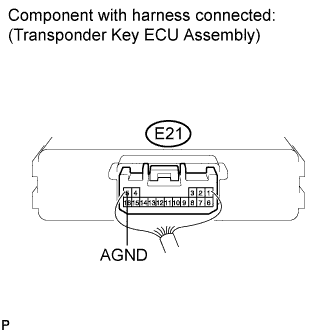
| 4.INSPECT TRANSPONDER KEY ECU ASSEMBLY (TRANSPONDER KEY AMPLIFIER GROUND) |
Measure the resistance according to the value(s) in the table below.
- Standard Resistance:
Tester Connection
| Condition
| Specified Condition
|
E21-5 (AGND) - Body ground
| Always
| Below 1 Ω
|