PERFORM ACTIVE TEST USING TECHSTREAM (CONTROL THE FUEL PUMP/SPEED)
INSPECT INSTRUMENT PANEL JUNCTION BLOCK (C/OPN RELAY INPUT VOLTAGE)
CHECK HARNESS AND CONNECTOR (INSTRUMENT PANEL JUNCTION BLOCK - INTEGRATION RELAY)
INSPECT INSTRUMENT PANEL JUNCTION BLOCK (C/OPN RELAY)
CHECK HARNESS AND CONNECTOR (C/OPN RELAY - ECM)
CHECK HARNESS AND CONNECTOR (INSTRUMENT PANEL JUNCTION BLOCK - FUEL PUMP)
CHECK HARNESS AND CONNECTOR (FUEL PUMP - BODY GROUND)
READ VALUE USING TECHSTREAM (STARTER SIGNAL)
READ VALUE USING TECHSTREAM (ENGINE SPEED)
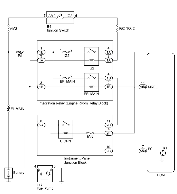
SFI SYSTEM - Fuel Pump Control Circuit |
DESCRIPTION
When the engine is cranked, the starter relay drive signal from the ignition switch is input into the STA terminal of the ECM, and the NE signal generated by the crankshaft position sensor is also input into the NE+ terminal. Thus, the ECM interprets that the engine is being cranked, and turns transistor Tr1 in the ECM internal circuit on. The current flows to the C/OPN (Circuit Opening) relay by turning Tr1 on. Then, the fuel pump operates.While the NE signal is input into the ECM, and the engine is running, the ECM turns Tr1 on continuously.

WIRING DIAGRAM
INSPECTION PROCEDURE
| 1.PERFORM ACTIVE TEST USING TECHSTREAM (CONTROL THE FUEL PUMP/SPEED) |
Connect the Techstream to the DLC3.
Turn the ignition switch to ON.
Turn the Techstream on.
Enter the following menus: Powertrain / Engine and ECT / Active Test / Control the Fuel Pump/Speed.
Check whether the fuel pump operating sound occurs when performing the Active Test using the Techstream.
- Result:
Result Proceed to Fuel pump operating sound does not occur A Fuel pump operating sound occurs B
|
| ||||
| A | |
| 2.INSPECT INSTRUMENT PANEL JUNCTION BLOCK (C/OPN RELAY INPUT VOLTAGE) |
Disconnect the instrument panel junction block connector.
Measure the voltage between the terminal of the instrument panel junction block and the body ground when the ignition switch is turned to ON and off.
- Standard Voltage:
Tester Connection Condition Specified Condition 2B-11 - Body ground Ignition switch off Below 1 V 2F-4 - Body ground 2B-11 - Body ground Ignition switch ON 11 to 14 V 2F-4 - Body ground
- Result:
Result Proceed to Outside standard range A Within standard range B
 |
Reconnect the instrument panel junction block connector.
|
| ||||
| A | |
| 3.CHECK HARNESS AND CONNECTOR (INSTRUMENT PANEL JUNCTION BLOCK - INTEGRATION RELAY) |
Remove the integration relay from the engine room relay block.
Disconnect the integration relay connector.
Disconnect the instrument panel junction block connectors.
Measure the resistance according to the value(s) in the table below.
- Standard Resistance (Check for Open):
Tester Connection Condition Specified Condition 1A-4 - 2F-4 Always Below 1 Ω 1B-4 - 2B-11 Always Below 1 Ω
Reconnect the integration relay connector.
Reinstall the integration relay.
Reconnect the instrument panel junction block connectors.
|
| ||||
| OK | ||
| ||
| 4.INSPECT INSTRUMENT PANEL JUNCTION BLOCK (C/OPN RELAY) |
Inspect the C/OPN relay (COROLLA_ZRE142 RM000003D38009X.html).
|
| ||||
| OK | |
| 5.CHECK HARNESS AND CONNECTOR (C/OPN RELAY - ECM) |
Disconnect the ECM connector.
Disconnect the instrument panel junction block connector.
Measure the resistance according to the value(s) in the table below.
- Standard Resistance (Check for Open):
Tester Connection Condition Specified Condition 2B-10 - A50-7 (FC) Always Below 1 Ω
- Standard Resistance (Check for Short):
Tester Connection Condition Specified Condition 2B-10 or A50-7 (FC) - Body ground Always 10 kΩ or higher
Reconnect the instrument panel junction block connector.
Reconnect the ECM connector.
|
| ||||
| OK | |
| 6.CHECK HARNESS AND CONNECTOR (INSTRUMENT PANEL JUNCTION BLOCK - FUEL PUMP) |
Disconnect the instrument panel junction block connector.
Disconnect the fuel pump connector.
Measure the resistance according to the value(s) in the table below.
- Standard Resistance (Check for Open):
Tester Connections Condition Specified Conditions 2A-8 - L17-4 (B) (Fuel pump) Always Below 1 Ω
- Standard Resistance (Check for Short):
Tester Connections Condition Specified Conditions 2A-8 or L17-4 (B) (Fuel pump) - Body ground Always 10 kΩ or higher
Reconnect the fuel pump connector.
Reconnect the instrument panel junction block connector.
|
| ||||
| OK | |
| 7.CHECK HARNESS AND CONNECTOR (FUEL PUMP - BODY GROUND) |
Disconnect the fuel pump connector.
Measure the resistance according to the value(s) in the table below.
- Standard Resistance (Check for Open):
Tester Connections Condition Specified Conditions L17-5 (E) (Fuel pump) - Body ground Always Below 1 Ω
Reconnect the fuel pump connector.
|
| ||||
| OK | |
| 8.READ VALUE USING TECHSTREAM (STARTER SIGNAL) |
Connect the Techstream to the DLC3.
Turn the ignition switch to ON.
Turn the Techstream on.
Enter the following menus: Powertrain / Engine and ECT / Data List / Primary / Starter Signal.
Check the result when the ignition switch is turned to ON and engine is started.
- Result:
Condition Starter Signal Ignition switch ON OFF (Starter signal off) Engine started ON (Starter signal on)
|
| ||||
| OK | |
| 9.READ VALUE USING TECHSTREAM (ENGINE SPEED) |
Connect the Techstream to the DLC3.
Turn the ignition switch to ON.
Turn the Techstream on.
Enter the following menus: Powertrain / Engine and ECT / Data List / Primary / Engine Speed.
Read the values displayed on the Techstream while cranking.
- OK:
- Values are displayed continuously.
|
| ||||
| OK | ||
| ||