Tire Pressure Warning System Tc And Cg Terminal Circuit
DESCRIPTION
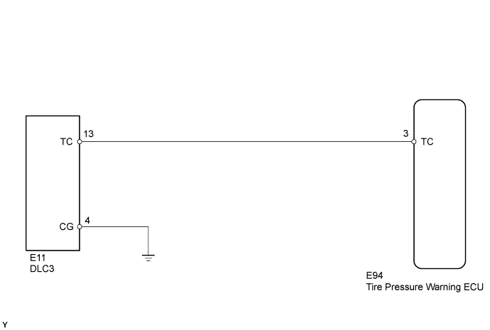
WIRING DIAGRAM
INSPECTION PROCEDURE
CHECK HARNESS AND CONNECTOR (DLC3 - TIRE PRESSURE WARNING ECU)
TIRE PRESSURE WARNING SYSTEM - TC and CG Terminal Circuit |
DESCRIPTION
DTC output mode is set by Connecting terminals 13 (TC) and 4 (CG) of the DLC3. The DTCs are indicated by the blinking of the tire pressure warning light.
WIRING DIAGRAM
- HINT:
- When various warning lights blinks continuously, a ground short in the wiring of terminal TC of the DLC3 or an internal ground short in an ECU connected to this circuit may have occurred.
INSPECTION PROCEDURE
- NOTICE:
- When replacing the tire pressure warning ECU, read the transmitter IDs stored in the old ECU using the Techstream and write them down before removal.
- It is necessary to perform initialization (COROLLA_ZRE142 RM000000XMZ07PX.html) after registration (COROLLA_ZRE142 RM000000XN108OX.html) of the transmitter IDs into the tire pressure warning ECU after the ECU has been replaced.
| 1.CHECK HARNESS AND CONNECTOR (DLC3 - TIRE PRESSURE WARNING ECU) |
Disconnect the E94 ECU connector.
Measure the resistance according to the value(s) in the table below.
- Standard Resistance:
Tester Connection
| Condition
| Specified Condition
|
E94-3 (TC) - E11-13 (TC)
| Always
| Below 1 Ω
|
E11-4 (CG) - Body ground
|
| | REPAIR OR REPLACE HARNESS OR CONNECTOR |
|
|