Anti-Lock Brake System Tc And Cg Terminal Circuit
Brake. Corolla. Zre142 Aze141
DESCRIPTION
WIRING DIAGRAM
INSPECTION PROCEDURE
CHECK CAN COMMUNICATION SYSTEM
INSPECT DLC3
CHECK HARNESS AND CONNECTOR (TC of DLC3 - ECM)
CHECK HARNESS AND CONNECTOR (CG of DLC3 - BODY GROUND)
CHECK ECM (TC of DLC3 INPUT)
ANTI-LOCK BRAKE SYSTEM - TC and CG Terminal Circuit |
DESCRIPTION
Connecting terminals TC and CG of the DLC3 causes the ECU to display the DTC by blinking the ABS warning light.
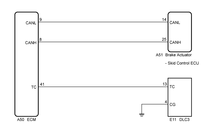
WIRING DIAGRAM
- HINT:
- When the warning lights continue to blink, a ground short in the wiring of terminal TC of the DLC3 or an internal ground short in one or more ECUs is suspected.
INSPECTION PROCEDURE
| 1.CHECK CAN COMMUNICATION SYSTEM |
Check if the CAN communication system DTC is output (COROLLA_ZRE142 RM000000XHV0F3X.html).
- Result:
Result
| Proceed to
|
DTC is not output
| A
|
DTC is output
| B
|
Turn the ignition switch to ON.
Measure the voltage according to the value(s) in the table below.
- Standard Voltage:
Tester Connection
| Switch Condition
| Specified Condition
|
E11-13 (TC) - E11-4 (CG)
| Ignition switch ON
| 11 to 14 V
|
- Result:
| 3.CHECK HARNESS AND CONNECTOR (TC of DLC3 - ECM) |
Turn the ignition switch off.
Disconnect the ECM connector.
Measure the resistance according to the value(s) in the table below.
- Standard Resistance:
Tester Connection
| Condition
| Specified Condition
|
E11-13 (TC) - A50-41 (TC)
| Always
| Below 1 Ω
|
E11-13 (TC) - Body ground
| Always
| 10 kΩ or higher
|
| | REPAIR OR REPLACE HARNESS OR CONNECTOR |
|
|
| 4.CHECK HARNESS AND CONNECTOR (CG of DLC3 - BODY GROUND) |
Measure the resistance according to the value(s) in the table below.
- Standard Resistance:
Tester Connection
| Condition
| Specified Condition
|
E11-4 (CG) - Body ground
| Always
| Below 1 Ω
|
| | REPAIR OR REPLACE HARNESS OR CONNECTOR |
|
|
| 5.CHECK ECM (TC of DLC3 INPUT) |
Turn the ignition switch off.
Reconnect the ECM connector.
Using SST, connect terminals TC and CG of the DLC3.
- SST
- 09843-18040
Turn the ignition switch to ON.
Check that the check engine warning light is blinking.
- Result:
Result
| Proceed to
|
Check engine warning light is blinking
| A
|
Check engine warning light is not blinking
| B
|
- HINT:
- If troubleshooting has been carried out according to the Problem Symptoms Table, refer back to the table and proceed to the next step before replacing the part (COROLLA_ZRE142 RM000000XHN0DVX.html).
| | REPAIR OR REPLACE WIRE HARNESS OR ECM (TC of ECM CIRCUIT) |
|
|