Dtc C1235/35 Foreign Object Is Attached On Tip Of Front Speed Sensor Rh
Brake. Corolla. Zre142 Aze141
DESCRIPTION
WIRING DIAGRAM
INSPECTION PROCEDURE
INSPECT SPEED SENSOR
CHECK HARNESS AND CONNECTOR (SKID CONTROL SENSOR WIRE)
CHECK HARNESS AND CONNECTOR (SKID CONTROL ECU - SPEED SENSOR)
INSPECT SKID CONTROL ECU (SENSOR INPUT)
RECONFIRM DTC
CHECK FRONT SPEED SENSOR TIP
CHECK FRONT SPEED SENSOR ROTOR
RECONFIRM DTC
REPLACE FRONT SPEED SENSOR
RECONFIRM DTC
REPLACE FRONT SPEED SENSOR ROTOR
RECONFIRM DTC
REPLACE REAR SPEED SENSOR AND REAR SPEED SENSOR ROTOR
RECONFIRM DTC
DTC C1235/35 Foreign Object is Attached on Tip of Front Speed Sensor RH |
DTC C1236/36 Foreign Object is Attached on Tip of Front Speed Sensor LH |
DTC C1238/38 Foreign Object is Attached on Tip of Rear Speed Sensor RH |
DTC C1239/39 Foreign Object is Attached on Tip of Rear Speed Sensor LH |
DTC C1275/75 Abnormal Change in Output Signal of Front Speed Sensor RH (Test Mode DTC) |
DTC C1276/76 Abnormal Change in Output Signal of Front Speed Sensor LH (Test Mode DTC) |
DTC C1277/77 Abnormal Change in Output Signal of Rear Speed Sensor RH (Test Mode DTC) |
DTC C1278/78 Abnormal Change in Output Signal of Rear Speed Sensor LH (Test Mode DTC) |
DESCRIPTION
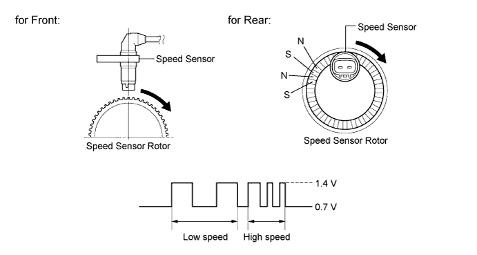
The speed sensor detects the wheel speed and sends the appropriate signals to the skid control ECU. These signals are used for the ABS control system.Speed sensor rotors have 48 serrations (for front) or rows of alternating N and S magnetic poles (for rear). The hall IC type speed sensor use the frequency of output pulses to detect the vehicle speed. Because the sensor outputs digital pulses, it can detect vehicle speeds even when the vehicle is nearly stationary.When foreign matter or oil adheres to the speed sensor tip or speed sensor rotor, these DTCs are output. An abnormal waveform input from the sensor determines these conditions.These DTCs may be detected when a malfunction occurs in the connector terminals or wire harness of the speed sensor circuit.DTCs C1275/75 to C1278/78 will be deleted when the speed sensor sends a vehicle speed signal or when Test Mode ends. DTCs C1275/75 to C1278/78 are output only in Test Mode.DTC Code
| DTC Detection Condition
| Trouble Area
|
C1235/35
C1236/36
C1238/38
C1239/39
| Either of the following is detected:
- At a vehicle speed of 20 km/h (12 mph) or more, the IG1 terminal voltage is 17.4 V or less, and noise occurs in the sensor signal from the abnormal wheel for 5 seconds or more.
- At a vehicle speed of 10 km/h (6 mph) or more, the IG1 terminal voltage is 17.4 V or less, and noise is input once per rotor rotation for 15 seconds or more.
| - Speed sensor
- Speed sensor rotor
- Sensor installation
- Brake actuator assembly (Skid control ECU)
|
C1275/75
C1276/76
C1277/77
C1278/78
| Detected only during Test Mode.
| Speed sensor rotor
|
- HINT:
- DTCs C1235/35 and C1275/75 are for the front speed sensor RH.
- DTCs C1236/36 and C1276/76 are for the front speed sensor LH.
- DTCs C1238/38 and C1277/77 are for the rear speed sensor RH.
- DTCs C1239/39 and C1278/78 are for the rear speed sensor LH.
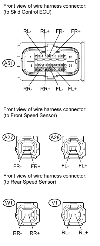
WIRING DIAGRAM
INSPECTION PROCEDURE
- HINT:
- When C0200/31, C0205/32, C0210/33 and/or C0215/34 is output together with C1235/35, C1236/36, C1238/38, or C1239/39, inspect and repair the trouble areas indicated by C0200/31, C0205/32, C0210/33 and/or C0215/34 first (COROLLA_ZRE142 RM000000XI90PBX.html for front, or COROLLA_ZRE142 RM000000XIA0I3X.html for rear).
Make sure that there is no looseness at the locking part and the connecting part of the connectors.
Disconnect each speed sensor connector.
Measure the resistance according to the value(s) in the table below.
- Standard Resistance:
- for RH:
Tester Connection
| Condition
| Specified Condition
|
2 (FR+) - Body ground
| Always
| 10 kΩ or higher
|
1 (FR-) - Body ground
| Always
| 10 kΩ or higher
|
2 (RR+) - Body ground
| Always
| 10 kΩ or higher
|
1 (RR-) - Body ground
| Always
| 10 kΩ or higher
|
- for LH:
Tester Connection
| Condition
| Specified Condition
|
2 (FL+) - Body ground
| Always
| 10 kΩ or higher
|
1 (FL-) - Body ground
| Always
| 10 kΩ or higher
|
2 (RL+) - Body ground
| Always
| 10 kΩ or higher
|
1 (RL-) - Body ground
| Always
| 10 kΩ or higher
|
- Result:
Result
| Proceed to
|
OK (for rear)
| A
|
OK (for front)
| B
|
NG
| C
|
- NOTICE:
- Check the speed sensor signal after replacement (COROLLA_ZRE142 RM000001JBD052X.html).
| 2.CHECK HARNESS AND CONNECTOR (SKID CONTROL SENSOR WIRE) |
Disconnect the skid control sensor wire.
Measure the resistance according to the value(s) in the table below.
- Standard Resistance:
- for RH:
Tester Connection
| Condition
| Specified Condition
|
W1 ("A"-2) - W1 ("B"-1)
| Always
| Below 1 Ω
|
W1 ("A"-2) - W1 ("B"-2)
| Always
| 10 kΩ or higher
|
W1 ("A"-2) - Body ground
| Always
| 10 kΩ or higher
|
W1 ("A"-1) - W1 ("B"-2)
| Always
| Below 1 Ω
|
W1 ("A"-1) - W1 ("B"-1)
| Always
| 10 kΩ or higher
|
W1 ("A"-1) - Body ground
| Always
| 10 kΩ or higher
|
- for LH:
Tester Connection
| Condition
| Specified Condition
|
V1 ("A"-2) - V1 ("B"-1)
| Always
| Below 1 Ω
|
V1 ("A"-2) - V1 ("B"-2)
| Always
| 10 kΩ or higher
|
V1 ("A"-2) - Body ground
| Always
| 10 kΩ or higher
|
V1 ("A"-1) - V1 ("B"-2)
| Always
| Below 1 Ω
|
V1 ("A"-1) - V1 ("B"-1)
| Always
| 10 kΩ or higher
|
V1 ("A"-1) - Body ground
| Always
| 10 kΩ or higher
|
- NOTICE:
- Check the speed sensor signal after replacement (COROLLA_ZRE142 RM000001JBD052X.html).
| | REPLACE SKID CONTROL SENSOR WIRE |
|
|
| 3.CHECK HARNESS AND CONNECTOR (SKID CONTROL ECU - SPEED SENSOR) |
Reconnect the skid control sensor wire.
Disconnect the skid control ECU connector.
Measure the resistance according to the value(s) in the table below.
- Standard Resistance:
- for RH:
Tester Connection
| Condition
| Specified Condition
|
A51-7 (FR+) - A27-2 (FR+)
| Always
| Below 1 Ω
|
A51-7 (FR+) - Body ground
| Always
| 10 kΩ or higher
|
A51-6 (FR-) - A27-1 (FR-)
| Always
| Below 1 Ω
|
A51-6 (FR-) - Body ground
| Always
| 10 kΩ or higher
|
A51-17 (RR+) - W1-2 (RR+)
| Always
| Below 1 Ω
|
A51-17 (RR+) - Body ground
| Always
| 10 kΩ or higher
|
A51-16 (RR-) - W1-1 (RR-)
| Always
| Below 1 Ω
|
A51-16 (RR-) - Body ground
| Always
| 10 kΩ or higher
|
- for LH:
Tester Connection
| Condition
| Specified Condition
|
A51-19 (FL+) - A28-2 (FL+)
| Always
| Below 1 Ω
|
A51-19 (FL+) - Body ground
| Always
| 10 kΩ or higher
|
A51-18 (FL-) - A28-1 (FL-)
| Always
| Below 1 Ω
|
A51-18 (FL-) - Body ground
| Always
| 10 kΩ or higher
|
A51-5 (RL+) - V1-2 (RL+)
| Always
| Below 1 Ω
|
A51-5 (RL+) - Body ground
| Always
| 10 kΩ or higher
|
A51-4 (RL-) - V1-1 (RL-)
| Always
| Below 1 Ω
|
A51-4 (RL-) - Body ground
| Always
| 10 kΩ or higher
|
| | REPAIR OR REPLACE HARNESS OR CONNECTOR |
|
|
| 4.INSPECT SKID CONTROL ECU (SENSOR INPUT) |
Reconnect the skid control ECU connector.
Turn the ignition switch to ON.
Measure the voltage according to the value(s) in the table below.
- Standard Voltage:
- for RH:
Tester Connection
| Switch Condition
| Specified Condition
|
A27-2 (FR+) - Body ground
| Ignition switch ON
| 8 to 14 V
|
W1-2 (RR+) - Body ground
| Ignition switch ON
| 8 to 14 V
|
- for LH:
Tester Connection
| Switch Condition
| Specified Condition
|
A28-2 (FL+) - Body ground
| Ignition switch ON
| 8 to 14 V
|
V1-2 (RL+) - Body ground
| Ignition switch ON
| 8 to 14 V
|
Turn the ignition switch off.
Reconnect the speed sensor connector.
Clear the DTCs (COROLLA_ZRE142 RM000000XHV0F3X.html).
Start the engine.
Drive the vehicle at a speed of 20 km/h (12 mph) or more for at least 60 seconds.
Check if the same DTC is recorded (COROLLA_ZRE142 RM000000XHV0F3X.html).
- Result:
Result
| Proceed to
|
DTCs (C1235/35, C1236/36, C1238/38 and/or C1239/39) are output (for front)
| A
|
DTCs (C1235/35, C1236/36, C1238/38 and/or C1239/39) are output (for rear)
| B
|
DTCs (C1235/35, C1236/36, C1238/38 and C1239/39) are not output
| C
|
| 6.CHECK FRONT SPEED SENSOR TIP |
Turn the ignition switch off.
Remove the front speed sensor (COROLLA_ZRE142 RM000002VPG01IX.html).
Check the speed sensor tip.
- OK:
- No scratches or foreign matter on the sensor tip.
- NOTICE:
- Check the speed sensor signal after cleaning or replacement (COROLLA_ZRE142 RM000001JBD052X.html).
| | CLEAN OR REPLACE FRONT SPEED SENSOR |
|
|
| 7.CHECK FRONT SPEED SENSOR ROTOR |
Remove the front speed sensor rotor (COROLLA_ZRE142 RM000001HAY03AX.html).
Check the speed sensor rotors.
- OK:
- No scratches, oil, or foreign matter on the rotors.
- NOTICE:
- Check the speed sensor signal after cleaning or replacement (COROLLA_ZRE142 RM000001JBD052X.html).
- HINT:
- If the front speed sensor rotor needs to be replaced, replace it together with the front axle outboard joint shaft assembly.
| | CLEAN OR REPLACE FRONT SPEED SENSOR ROTOR |
|
|
Install the front speed sensor and the front speed sensor rotor.
Clear the DTCs (COROLLA_ZRE142 RM000000XHV0F3X.html).
Start the engine.
Drive the vehicle at a speed of 20 km/h (12 mph) or more for at least 60 seconds.
Check if the same DTC is recorded (COROLLA_ZRE142 RM000000XHV0F3X.html).
- Result:
Result
| Proceed to
|
DTCs (C1235/35, C1236/36, C1238/38 and/or C1239/39) are output
| A
|
DTCs (C1235/35, C1236/36, C1238/38 and C1239/39) are not output
| B
|
| 9.REPLACE FRONT SPEED SENSOR |
Turn the ignition switch off.
Replace the front speed sensor (COROLLA_ZRE142 RM000002VPG01IX.html).
- NOTICE:
- Check the speed sensor signal after replacement (COROLLA_ZRE142 RM000001JBD052X.html).
Clear the DTCs (COROLLA_ZRE142 RM000000XHV0F3X.html).
Start the engine.
Drive the vehicle at a speed of 20 km/h (12 mph) or more for at least 60 seconds.
Check if the same DTC is recorded (COROLLA_ZRE142 RM000000XHV0F3X.html).
- Result:
Result
| Proceed to
|
DTCs (C1235/35, C1236/36, C1238/38 and/or C1239/39) are output
| A
|
DTCs (C1235/35, C1236/36, C1238/38 and C1239/39) are not output
| B
|
| 11.REPLACE FRONT SPEED SENSOR ROTOR |
Turn the ignition switch off.
Remove the front drive shaft assembly (COROLLA_ZRE142 RM000001HAY03AX.html).
Replace the front axle outboard joint shaft assembly (front speed sensor rotor) (COROLLA_ZRE142 RM000001IWA03MX.html).
- HINT:
- If the front speed sensor rotor needs to be replaced, replace it together with the front axle outboard joint shaft assembly.
- NOTICE:
- Check the speed sensor signal after replacement (COROLLA_ZRE142 RM000001JBD052X.html).
Install the front drive shaft assembly.
Clear the DTCs (COROLLA_ZRE142 RM000000XHV0F3X.html).
Start the engine.
Drive the vehicle at a speed of 20 km/h (12 mph) or more for at least 60 seconds.
Check if the same DTC is recorded (COROLLA_ZRE142 RM000000XHV0F3X.html).
- Result:
Result
| Proceed to
|
DTCs (C1235/35, C1236/36, C1238/38 and/or C1239/39) are output
| A
|
DTCs (C1235/35, C1236/36, C1238/38 and C1239/39) are not output
| B
|
| 13.REPLACE REAR SPEED SENSOR AND REAR SPEED SENSOR ROTOR |
Turn the ignition switch off.
Replace the rear speed sensor (COROLLA_ZRE142 RM000002VPC02SX.html).
Replace the rear axle hub and bearing assembly (rear speed sensor rotor) (COROLLA_ZRE142 RM000001Y1R05IX.html).
- HINT:
- The rear speed sensor rotor is incorporated into the rear axle hub and bearing assembly.
- If the rear speed sensor rotor needs to be replaced, replace it together with the rear axle hub and bearing assembly with rear speed sensor.
- NOTICE:
- Check the speed sensor signal after replacement (COROLLA_ZRE142 RM000001JBD052X.html).
Clear the DTCs (COROLLA_ZRE142 RM000000XHV0F3X.html).
Start the engine.
Drive the vehicle at a speed of 20 km/h (12 mph) or more for at least 60 seconds.
Check if the same DTC is recorded (COROLLA_ZRE142 RM000000XHV0F3X.html).
- Result:
Result
| Proceed to
|
DTCs (C1235/35, C1236/36, C1238/38 and/or C1239/39) are output
| A
|
DTCs (C1235/35, C1236/36, C1238/38 and C1239/39) are not output
| B
|