Vehicle Exterior. Corolla. Zre142 Aze141
Window Glass. Corolla. Zre142 Aze141
Window Defogger System (For Automatic Air Conditioning System) -- Terminals Of Ecu |
| CHECK AIR CONDITIONING AMPLIFIER ASSEMBLY |
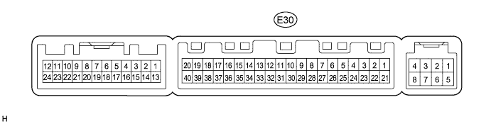
Disconnect the E30 air conditioning amplifier connector.
Measure the voltage according to the value(s) in the table below.
- Standard Voltage:
Tester Connection Wiring Color Terminal Description Condition Specified Condition E30-38 (RDFG) - E30-14 (GND) B - W-B*1
BE - W-B*2Rear defogger signal Ignition switch ON, Rear window defogger switch OFF 11 to 14 V E30-38 (RDFG) - E30-14 (GND) B - W-B*1
BE - W-B*2Rear defogger signal Ignition switch ON, Rear window defogger switch ON Below 1 V E30-1 (IG+) - E30-14 (GND) Y - W-B*1
R - W-B*2Power source (IG) Ignition switch ON 11 to 14 V E30-1 (IG+) - E30-14 (GND) Y - W-B*1
R - W-B*2Power source (IG) Ignition switch off Below 1 V E30-21 (B) - E30-14 (GND) W - W-B*1
BR - W-B*2Power source (Back-up) Always 11 to 14 V
- *1: for TMC Made
- *2: Except for TMC made
Measure the resistance according to the value(s) in the table below.
- Standard Resistance:
Tester Connection Wiring Color Terminal Description Condition Specified Condition E30-14 (GND) - Body ground W-B - Body ground Ground Always Below 1 Ω
| CHECK AIR CONDITIONING CONTROL ASSEMBLY |
Disconnect the E16 air conditioning control connector.

Measure the voltage according to the value(s) in the table below.
- Standard Voltage:
Tester Connection Wiring Color Terminal Description Condition Specified Condition E16-5 (IG+) - E16-2 (GND) B - W-B*1
V - W-B*2Power source (IG) Ignition switch ON 11 to 14 V E16-5 (IG+) - E16-2 (GND) B - W-B*1
V - W-B*2Power source (IG) Ignition switch off Below 1 V
- *1: for TMC Made
- *2: Except for TMC made
Measure the resistance according to the value(s) in the table below.
- Standard Resistance:
Tester Connection Wiring Color Terminal Description Condition Specified Condition E16-2 (GND) - Body ground W-B - Body ground Ground Always Below 1 Ω
| CHECK MAIN BODY ECU (INSTRUMENT PANEL JUNCTION BLOCK) |
Disconnect the 2G, 2F and 2Q instrument panel junction block connector.
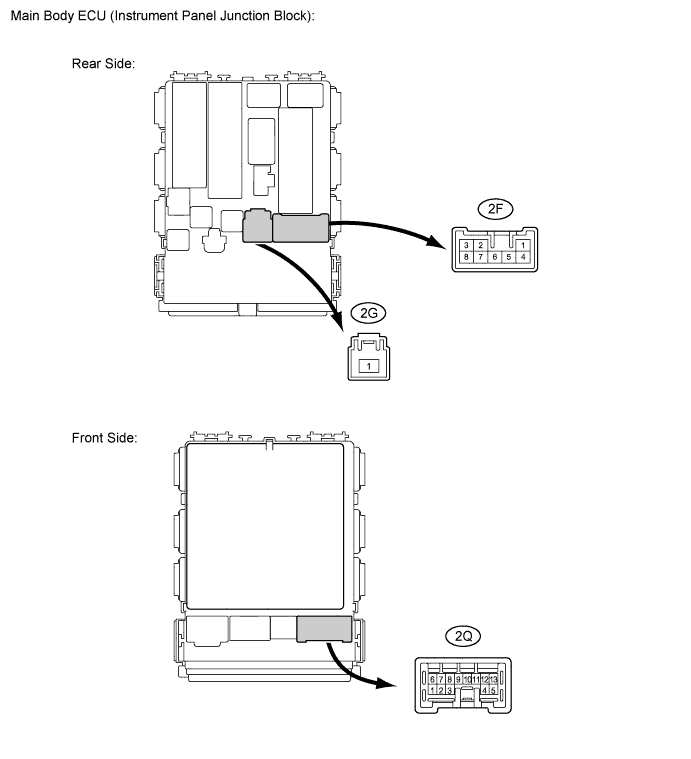
Measure the voltage according to the value(s) in the table below.
- Standard Voltage:
Tester Connection Wiring Color Terminal Description Condition Specified Condition 2G-1 - Body ground W - Body ground Power source Always 11 to 14 V 2Q-12 - Body ground B - Body ground*1
BE - Body ground*2DEF relay operation signal Ignition switch ON, Rear window defogger switch OFF 11 to 14 V 2Q-12 - Body ground B - Body ground*1
BE - Body ground*2DEF relay operation signal Ignition switch ON, Rear window defogger switch ON Below 1 V 2F-2 - Body ground B - Body ground Defogger wire operation signal Ignition switch ON, Rear window defogger switch OFF Below 1 V 2F-2 - Body ground B - Body ground Defogger wire operation signal Ignition switch ON, Rear window defogger switch ON 11 to 14 V
- *1: for TMC Made
- *2: Except for TMC made