Dtc B1451/51 Compressor Solenoid Circuit
DESCRIPTION
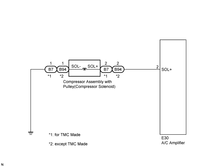
WIRING DIAGRAM
INSPECTION PROCEDURE
INSPECT COMPRESSOR ASSEMBLY WITH PULLEY
CHECK HARNESS AND CONNECTOR (COMPRESSOR ASSEMBLY WITH PULLEY - BODY GROUND)
CHECK HARNESS AND CONNECTOR (COMPRESSOR ASSEMBLY WITH PULLEY - A/C AMPLIFIER)
DTC B1451/51 Compressor Solenoid Circuit |
DESCRIPTION
Through this circuit, the compressor assembly with pulley receives a refrigerant compression demand signal from the air conditioning amplifier.Based on this signal, the compressor assembly with pulley changes the amount of compressor output.DTC No.
| DTC Detection Condition
| Trouble Area
|
B1451/51
| Open or short in compressor assembly with pulley (compressor solenoid) circuit
| - Compressor assembly with pulley (compressor solenoid)
- Harness or connector between A/C amplifier and compressor assembly with pulley (compressor solenoid)
- A/C amplifier
|
WIRING DIAGRAM
INSPECTION PROCEDURE
| 1.INSPECT COMPRESSOR ASSEMBLY WITH PULLEY |
Disconnect the compressor assembly with pulley (compressor solenoid) connector.
Measure the resistance according to the value(s) in the table below.
- Standard Resistance:
Tester Connection
| Condition
| Specified Condition
|
B7-2 (SOL+) - B7-1 (SOL-)*1
| 20°C (68°F)
| 10 to 11 Ω
|
B94-2 (SOL+) - B94-1 (SOL-)*2
| 20°C (68°F)
| 10 to 11 Ω
|
- *1: for TMC Made
- *2: except TMC Made
Text in Illustration*A
| for TMC Made
|
*B
| except TMC Made
|
*a
| Component without harness connected
(Compressor Assembly with Pulley (Compressor Solenoid))
|
- Result:
Result
| Proceed to
|
OK
| A
|
NG
(for 2AZ-FE)
| B
|
NG
(for 2ZR-FE)
| C
|
| 2.CHECK HARNESS AND CONNECTOR (COMPRESSOR ASSEMBLY WITH PULLEY - BODY GROUND) |
Measure the resistance according to the value(s) in the table below.
- Standard Resistance:
Tester Connection
| Condition
| Specified Condition
|
B7-1 (SOL-) - Body ground*1
| Always
| Below 1 Ω
|
B94-1 (SOL-) - Body ground*2
| Always
| Below 1 Ω
|
- *1: for TMC Made
- *2: except TMC Made
Text in Illustration*A
| for TMC Made
|
*B
| except TMC Made
|
*a
| Front view of wire harness connector
(to Compressor Assembly with Pulley (Compressor Solenoid))
|
| | REPAIR OR REPLACE HARNESS OR CONNECTOR |
|
|
| 3.CHECK HARNESS AND CONNECTOR (COMPRESSOR ASSEMBLY WITH PULLEY - A/C AMPLIFIER) |
Disconnect the A/C amplifier connector.
Measure the resistance according to the value(s) in the table below.
- Standard Resistance:
Tester Connection
| Condition
| Specified Condition
|
E30-2 (SOL+) - B7-2 (SOL+)*1
| Always
| Below 1 Ω
|
E30-2 (SOL+) - B94-2 (SOL+)*2
| Always
| Below 1 Ω
|
E30-2 (SOL+) - Body ground
| Always
| 10 kΩ or higher
|
- *1: for TMC Made
- *2: except TMC Made
- Result:
Result
| Proceed to
|
NG
| A
|
OK (When troubleshooting according to Problem Symptoms Table)
| B
|
OK (When troubleshooting according to DTC)
| C
|
| A |
|
|
|
| REPAIR OR REPLACE HARNESS OR CONNECTOR |
|