Air Conditioning System (For Automatic Air Conditioning System) Blower Motor Circuit
DESCRIPTION
WIRING DIAGRAM
INSPECTION PROCEDURE
PERFORM ACTIVE TEST USING TECHSTREAM
CHECK HARNESS AND CONNECTOR (BLOWER MOTOR - BODY GROUND)
CHECK HARNESS AND CONNECTOR (BLOWER MOTOR - BATTERY)
CHECK HARNESS AND CONNECTOR (A/C AMPLIFIER - BLOWER MOTOR)
INSPECT BLOWER MOTOR
INSPECT AIR CONDITIONING AMPLIFIER
AIR CONDITIONING SYSTEM (for Automatic Air Conditioning System) - Blower Motor Circuit |
DESCRIPTION
The blower motor is operated by signals from the A/C amplifier. Blower motor speed signals are transmitted in accordance with changes in the duty ratio.
WIRING DIAGRAM
INSPECTION PROCEDURE
- NOTICE:
- Inspect the fuses for circuits related to this system before performing the following inspection procedure.
| 1.PERFORM ACTIVE TEST USING TECHSTREAM |
Connect the Techstream to the DLC3.
Turn the ignition switch to ON.
Turn the Techstream on.
Enter the following menus: Body Electrical / Air Conditioner / Active Test.
Check the operation by referring to the table below.
Air ConditionerTester Display
| Test Part
| Control Range
| Diagnostic Note
|
Blower Motor
(Blower Motor)
| Blower motor
| Min.: 0, Max.: 31
| -
|
- Result:
Result
| Proceed to
|
OK
| A
|
NG (blower motor does not operate)
| B
|
NG (blower motor operates but does not change speed)
| C
|
| 2.CHECK HARNESS AND CONNECTOR (BLOWER MOTOR - BODY GROUND) |
Disconnect the blower motor connector.
Measure the resistance according to the value(s) in the table below.
- Standard Resistance:
Tester Connection
| Condition
| Specified Condition
|
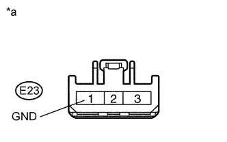
E23-1 (GND) - Body ground
| Always
| Below 1 Ω
|
Text in Illustration*a
| Front view of wire harness connector
(to Blower Motor)
|
| | REPAIR OR REPLACE HARNESS OR CONNECTOR |
|
|
| 3.CHECK HARNESS AND CONNECTOR (BLOWER MOTOR - BATTERY) |
Disconnect the blower motor connector.
Measure the voltage according to the value(s) in the table below.
- Standard Voltage:
Tester Connection
| Condition
| Specified Condition
|
E23-3 (+B) - Body ground
| Always
| 11 to 14 V
|
Text in Illustration*a
| Front view of wire harness connector
(to Blower Motor)
|
| | REPAIR OR REPLACE HARNESS OR CONNECTOR |
|
|
| 4.CHECK HARNESS AND CONNECTOR (A/C AMPLIFIER - BLOWER MOTOR) |
Disconnect the A/C amplifier connector.
Measure the resistance according to the value(s) in the table below.
- Standard Resistance:
Tester Connection
| Condition
| Specified Condition
|
E23-2 (SI) - E30-23 (BLW)
| Always
| Below 1 Ω
|
E23-2 (SI) - Body ground
| Always
| 10 kΩ or higher
|
| | REPAIR OR REPLACE HARNESS OR CONNECTOR |
|
|
Reconnect the connector to the blower motor.
Measure the voltage on the A/C amplifier connector side according to the value(s) in the table below.
- Standard Voltage:
Tester Connection
| Switch Condition
| Specified Condition
|
E30-23 (BLW) - Body ground
| Ignition switch ON
| 4.5 to 5.5 V
|
Text in Illustration*a
| Front view of wire harness connector
(to A/C Amplifier)
|
| 6.INSPECT AIR CONDITIONING AMPLIFIER |
Remove the A/C amplifier.
Reconnect the connector to the A/C amplifier.
Turn the ignition switch to ON.
Turn the blower switch on.
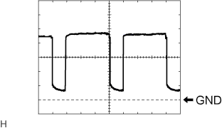
Measure the waveform between terminal E30-23 (BLW) of the A/C amplifier and body ground.
Item
| Content
|
Tool setting
| 1 V/DIV., 500 μs./DIV.
|
Vehicle condition
| Ignition switch ON
Blower switch: ON
|
- OK:
- Waveform is as shown in the illustration.
- HINT:
- Waveform varies with the blower level.
Text in Illustration*a
| Component with harness connected
(A/C Amplifier)
|