Air Conditioning System (For Manual Air Conditioning System) Ig Power Source Circuit
DESCRIPTION
WIRING DIAGRAM
INSPECTION PROCEDURE
CHECK HARNESS AND CONNECTOR (AIR CONDITIONING AMPLIFIER - BATTERY)
CHECK HARNESS AND CONNECTOR (AIR CONDITIONING AMPLIFIER - BODY GROUND)
AIR CONDITIONING SYSTEM (for Manual Air Conditioning System) - IG Power Source Circuit |
DESCRIPTION
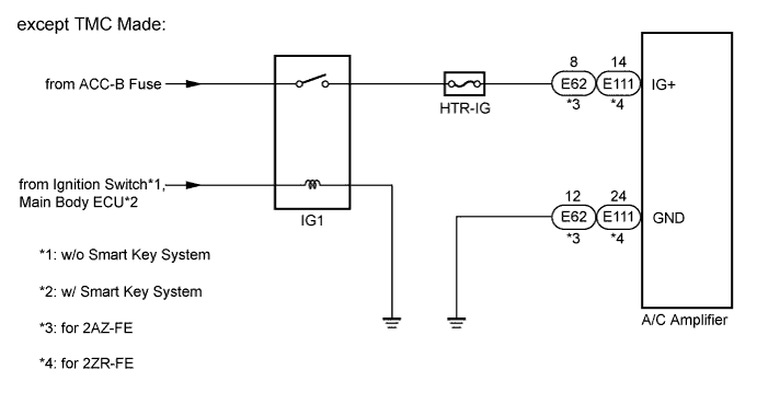
The main power source is supplied to the A/C amplifier when the ignition switch is turned to ON.The power source is used for operating the A/C amplifier and servo motor, etc.
WIRING DIAGRAM
INSPECTION PROCEDURE
- NOTICE:
- Inspect the fuses for circuits related to this system before performing the following inspection procedure.
- HINT:
- Start the engine before inspection. Check the IG1 relay or battery if the engine does not start.
| 1.CHECK HARNESS AND CONNECTOR (AIR CONDITIONING AMPLIFIER - BATTERY) |
Disconnect the connector from the A/C amplifier.
Measure the voltage according to the value(s) in the table below.
- Standard Voltage:
Tester Connection
| Switch Condition
| Specified Condition
|
E62-8 (IG+) - Body ground*1
| Ignition switch off
| Below 1 V
|
Ignition switch ON
| 11 to 14 V
|
E111-14 (IG+) - Body ground*2
| Ignition switch off
| Below 1 V
|
Ignition switch ON
| 11 to 14 V
|
- *1: except TMC Made 2AZ-FE
- *2: for TMC Made and except TMC Made 2ZR-FE
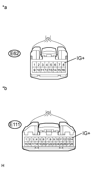
Text in Illustration*a
| Front view of wire harness connector
(to A/C Amplifier (except TMC Made 2AZ-FE))
|
*b
| Front view of wire harness connector
(to A/C Amplifier (for TMC Made and except TMC Made 2ZR-FE))
|
| | REPAIR OR REPLACE HARNESS OR CONNECTOR |
|
|
| 2.CHECK HARNESS AND CONNECTOR (AIR CONDITIONING AMPLIFIER - BODY GROUND) |
Measure the resistance according to the value(s) in the table below.
- Standard Resistance:
Tester Connection
| Condition
| Specified Condition
|
E62-12 (GND) - Body ground*1
| Always
| Below 1 Ω
|
E111-24 (GND) - Body ground*2
| Always
| Below 1 Ω
|
- *1: except TMC Made 2AZ-FE
- *2: for TMC Made and except TMC Made 2ZR-FE
| | REPAIR OR REPLACE HARNESS OR CONNECTOR |
|
|