Toyota Parking Assist-Sensor System Clearance Sonar Main Switch Circuit
DESCRIPTION
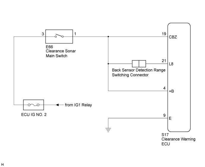
WIRING DIAGRAM
INSPECTION PROCEDURE
INSPECT FUSE (ECU IG NO. 2)
CHECK HARNESS AND CONNECTOR (CLEARANCE WARNING ECU - CLEARANCE SONAR MAIN SWITCH)
CHECK HARNESS AND CONNECTOR (CLEARANCE WARNING ECU - CLEARANCE SONAR MAIN SWITCH)
INSPECT CLEARANCE SONAR MAIN SWITCH
TOYOTA PARKING ASSIST-SENSOR SYSTEM - Clearance Sonar Main Switch Circuit |
DESCRIPTION
When the clearance sonar main switch is turned on, an on signal is sent to the clearance warning ECU.The Toyota parking assist-sensor system starts operating when the on signal is input to the clearance warning ECU S17-19 (CBZ) terminal (power source terminal).If the clearance warning ECU S17-19 (CBZ) terminal is receiving the on signal but the S17-4 (+B) terminal (corner sensor detection range adjusting terminal) does not receive the signal, the Toyota parking assist-sensor system will operate but the detection range of the corner sensors will become narrower.When the corner sensor detection range becomes narrower, the detection range will not change in the front (approximately 500 mm (19.69 in.)), but will change to approximately 500 mm (19.69 in.) or less around the corner sensors.When the back sensor detection range switching connector is connected, the clearance warning ECU S17-22 (L8) terminal (back sensor detection range switching terminal) will receive an on signal. As a result, the short detection range will be 500 +/- 50 mm (19.69 +/- 1.97 in.).When the back sensor detection range switching connector is disconnected, the clearance warning ECU S17-22 (L8) terminal (back sensor detection range switching terminal) will not receive an on signal. As a result, the short detection range for the back sensors will be 700 +/- 70 mm (27.56 +/- 2.76 in.).In addition, when the back sensor detection range switching connector circuit has an open or short circuit, the clearance warning ECU S17-22 (L8) terminal (back sensor detection range switching terminal) will not receive an on signal. As a result, the short detection range for the back sensors will be 700 +/- 70 mm (27.56 +/- 2.76 in.).WIRING DIAGRAM
INSPECTION PROCEDURE
- NOTICE:
- When inspecting the vehicle side wire harness for the clearance sonar main switch and clearance warning ECU, proper inspection cannot be done if the back sensor detection range switching connector is disconnected.
- Be sure to inspect the vehicle side wire harness for the clearance sonar main switch and clearance warning ECU with the back sensor detection range switching connector connected.
| 1.INSPECT FUSE (ECU IG NO. 2) |
Remove the ECU IG NO. 2 fuse from the main body ECU (instrument panel junction block).
Measure the resistance according to the value(s) in the table below.
- Standard Resistance:
Tester Connection
| Condition
| Specified Condition
|
ECU IG NO. 2 fuse
| Always
| Below 1 Ω
|
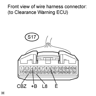
| 2.CHECK HARNESS AND CONNECTOR (CLEARANCE WARNING ECU - CLEARANCE SONAR MAIN SWITCH) |
Disconnect the S17 connector from the clearance warning ECU.
Measure the voltage according to the value(s) in the table below.
- Standard Voltage:
Tester Connection
| Switch Condition
| Specified Condition
|
S17-4 (+B) - S17-9 (E)
| Ignition switch ON, Clearance sonar main switch ON
| 11 to 14 V
|
S17-19 (CBZ) - S17-9 (E)
| Ignition switch ON, Clearance sonar main switch ON
| 11 to 14 V
|
S17-21 (L8) - S17-9 (E)
| Ignition switch ON, Clearance sonar main switch ON, Back sensor detection range switching connector connected
| 11 to 14 V
|
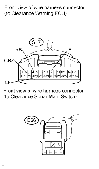
| 3.CHECK HARNESS AND CONNECTOR (CLEARANCE WARNING ECU - CLEARANCE SONAR MAIN SWITCH) |
Disconnect the S17 connector from the clearance warning ECU.
Disconnect the E66 connector from the clearance sonar main switch.
Measure the resistance according to the value(s) in the table below.
- Standard Resistance:
Tester Connection
| Condition
| Specified Condition
|
S17-4 (+B) - E66-1
| Always
| Below 1 Ω
|
S17-19 (CBZ) - E66-1
| Always
| Below 1 Ω
|
S17-21 (L8) - E66-1
| Back sensor detection range switching connector connected
| Below 1 Ω
|
S17-4 (+B) - Body ground
| Always
| 10 kΩ or higher
|
S17-9 (E) - Body ground
| Always
| Below 1 Ω
|
S17-19 (CBZ) - Body ground
| Always
| 10 kΩ or higher
|
S17-21 (L8) - Body ground
| Back sensor detection range switching connector connected
| 10 kΩ or higher
|
| | REPAIR OR REPLACE HARNESS OR CONNECTOR |
|
|
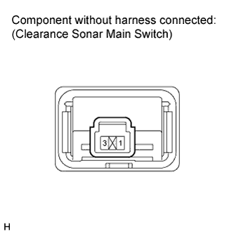
| 4.INSPECT CLEARANCE SONAR MAIN SWITCH |
Remove the clearance sonar main switch (CAMRY_ACV40 RM000003GR8000X.html).
Measure the resistance according to the value(s) in the table below.
- Standard Resistance:
Tester Connection
| Switch Condition
| Specified Condition
|
E66-1 - E66-3
| Clearance sonar main switch OFF
| 10 kΩ or higher
|
E66-1 - E66-3
| Clearance sonar main switch ON
| Below 1 Ω
|
| OK |
|
|
|
| REPAIR OR REPLACE HARNESS OR CONNECTOR |
|