Toyota Parking Assist-Sensor System Parking Brake Switch Circuit
DESCRIPTION
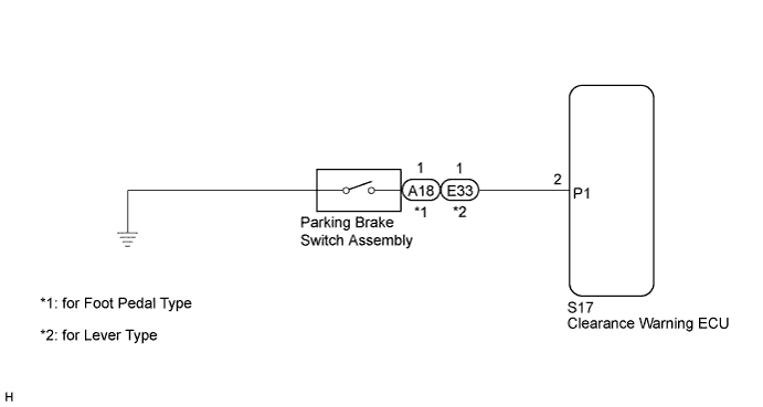
WIRING DIAGRAM
INSPECTION PROCEDURE
CONFIRM MODEL
CHECK HARNESS AND CONNECTOR (CLEARANCE WARNING ECU - PARKING BRAKE SWITCH ASSEMBLY)
INSPECT PARKING BRAKE SWITCH ASSEMBLY
CHECK HARNESS AND CONNECTOR
INSPECT PARKING BRAKE SWITCH ASSEMBLY
TOYOTA PARKING ASSIST-SENSOR SYSTEM - Parking Brake Switch Circuit |
DESCRIPTION
The parking brake switch assembly turns on and off according to the operation of the parking brake lever (for M/T) or parking brake pedal (for A/T).The clearance warning ECU stops detection operation when it receives an on signal from the parking brake switch.
WIRING DIAGRAM
INSPECTION PROCEDURE
Choose the model to be inspected.
- Result:
Model
| Proceed to
|
for Foot Pedal Type
| A
|
for Lever Type
| B
|
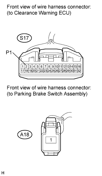
| 2.CHECK HARNESS AND CONNECTOR (CLEARANCE WARNING ECU - PARKING BRAKE SWITCH ASSEMBLY) |
Disconnect the S17 connector from the clearance warning ECU.
Disconnect the A18 connector from the parking brake switch assembly.
Measure the resistance according to the value(s) in the table below.
- Standard Resistance:
Tester Connection
| Condition
| Specified Condition
|
S17-2 (P1) - A18-1
| Always
| Below 1 Ω
|
S17-2 (P1) - Body ground
| Always
| 10 kΩ or higher
|
| | REPAIR OR REPLACE HARNESS OR CONNECTOR |
|
|
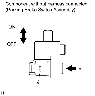
| 3.INSPECT PARKING BRAKE SWITCH ASSEMBLY |
Remove the parking brake switch assembly.
Measure the resistance according to the value(s) in the table below.
- Standard Resistance:
Tester Connection
| Switch Condition
| Specified Condition
|
Switch connector (A) - Switch body (B)
| ON (When shaft is not pressed)
| Below 1 Ω
|
Switch connector (A) - Switch body (B)
| OFF (When shaft is pressed)
| 10 kΩ or higher
|
| | REPLACE PARKING BRAKE SWITCH ASSEMBLY |
|
|
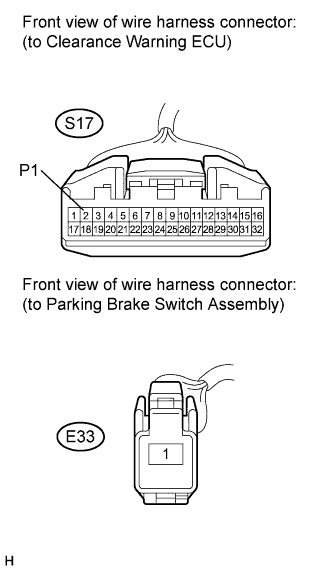
| 4.CHECK HARNESS AND CONNECTOR |
Disconnect the S17 connector from the clearance warning ECU.
Disconnect the E33 connector from the parking brake switch assembly.
Measure the resistance according to the value(s) in the table below.
- Standard Resistance:
Tester Connection
| Condition
| Specified Condition
|
S17-2 (P1) - E33-1
| Always
| Below 1 Ω
|
S17-2 (P1) - Body ground
| Always
| 10 kΩ or higher
|
| | REPAIR OR REPLACE HARNESS OR CONNECTOR |
|
|
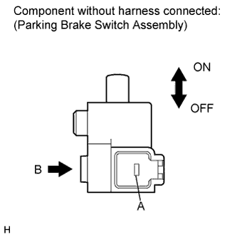
| 5.INSPECT PARKING BRAKE SWITCH ASSEMBLY |
Remove the parking brake switch assembly.
Measure the resistance according to the value(s) in the table below.
- Standard Resistance:
Tester Connection
| Switch Condition
| Specified Condition
|
Switch connector (A) - Switch body (B)
| ON (When shaft is not pressed)
| Below 1 Ω
|
Switch connector (A) - Switch body (B)
| OFF (When shaft is pressed)
| 10 kΩ or higher
|
| | REPLACE PARKING BRAKE SWITCH ASSEMBLY |
|
|