Communication System. Camry. Acv40 Gsv40
Multiplex Communication. Camry. Acv40 Gsv40
Lin Communication System -- Terminals Of Ecu |
| CHECK MAIN BODY ECU (INSTRUMENT PANEL JUNCTION BLOCK) |
Disconnect the ID and IF instrument panel junction block connectors.
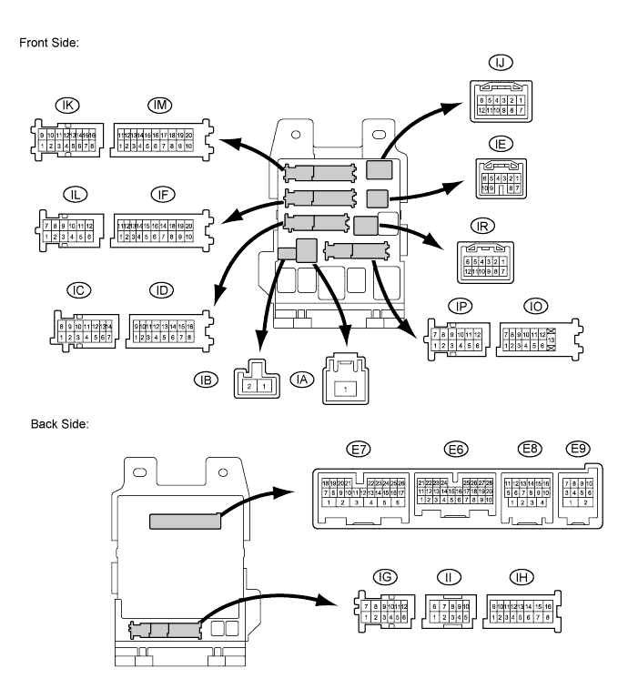
Measure the voltage and resistance according to the value(s) in the table below.
If the result is not as specified, there may be a malfunction on the wire harness side.Terminal No. (Symbols) Wiring Color Terminal Description Condition Specified Condition ID-10 (BECU) - Body ground O - Body ground Battery power supply Always 11 to 14 V IF-10 (GND1) - Body ground W-B - Body ground Ground Always Below 1 Ω Reconnect the ID and IF instrument panel junction block connectors.
Measure the pulse according to the value(s) in the table below.
If the result is not as specified, the main body ECU (Instrument panel junction block) may have a malfunction.Terminal No. (Symbols) Wiring Color Terminal Description Condition Specified Condition E8-10 (LIN2) - IF-10 (GND1) P - W-B LIN Communication line Ignition switch ON Pulse generation
| CHECK POWER WINDOW REGULATOR MOTOR (DRIVER SIDE) |
Disconnect the I5*1 or H10*2 motor connector.
- HINT:
- *1: for LHD
- *2: for RHD

Measure the voltage and resistance according to the value(s) in the table below.
Terminal No. (Symbols) Wiring Color Terminal Description Condition Specified Condition I5-2 (B) - I5-1 (E)*1
H10-2 (B) - H10-1 (E)*2W - W-B Battery power supply Always 11 to 14 V I5-1 (E) - Body ground*1
H10-1 (E) - Body ground*2W-B - Body ground Ground Always Below 1 Ω - HINT:
- *1: for LHD
- *2: for RHD
Reconnect the I5*1 or H10*2 motor connector.
- HINT:
- *1: for LHD
- *2: for RHD
Measure the pulse according to the value(s) in the table below.
Terminal No. (Symbols) Wiring Color Terminal Description Condition Specified Condition I5-9 (LIN) - I5-1 (E)*1
H10-9 (LIN) - H10-1 (E)*2P - W-B LIN Communication line Ignition switch ON Pulse generation - HINT:
- *1: for LHD
- *2: for RHD
| CHECK SLIDING ROOF ECU (SLIDING ROOF DRIVE GEAR SUB-ASSEMBLY)* |
- HINT:
- *: Models with Sliding Roof System
Disconnect the Q12 ECU connector.

Measure the voltage and resistance according to the value(s) in the table below.
If the result is not as specified, there may be a malfunction on the wire harness side.Terminal No. (Symbols) Wiring Color Terminal Description Condition Specified Condition Q12-1 (B) - Q12-2 (E) B - W-B Battery power supply Always 11 to 14 V Q12-2 (E) - Body ground W-B - Body ground Ground Always Below 1 Ω Reconnect the Q12 ECU connector.
Measure the pulse according to the value(s) in the table below.
If the result is not as specified, the motor may be malfunctioning.Terminal No. (Symbols) Wiring Color Terminal Description Condition Specified Condition Q12-4 (MPX1) - Q12-2 (E) P - W-B LIN Communication line Ignition switch ON Pulse generation