Navigation System Navigation Receiver Assembly Power Source Circuit
DESCRIPTION
WIRING DIAGRAM
INSPECTION PROCEDURE
INSPECT NAVIGATION RECEIVER ASSEMBLY
NAVIGATION SYSTEM - Navigation Receiver Assembly Power Source Circuit |
DESCRIPTION
This is the power source circuit to operate the navigation receiver assembly.
WIRING DIAGRAM
INSPECTION PROCEDURE
| 1.INSPECT NAVIGATION RECEIVER ASSEMBLY |
Disconnect the navigation receiver assembly connector.
Disconnect the navigation receiver assembly connector.
Measure the resistance according to the value(s) in the table below .
- Standard Resistance:
Tester Connection
| Condition
| Specified Condition
|
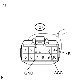
F27-7 (GND) - Body ground
| Always
| Below 1 Ω
|
Measure the voltage according to the value(s) in the table below.
- Standard Voltage:
Tester Connection
| Condition
| Specified Condition
|
F27-4 (B) - F27-7 (GND)
| Always
| 11 to 14 V
|
F27-3 (ACC) - F27-7 (GND)
| Ignition switch ACC
| 11 to 14 V
|
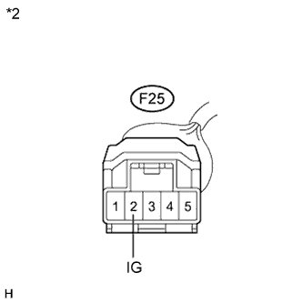
F25-2 (IG) - F27-7 (GND)
| Ignition switch ON
| 11 to 14 V
|
Text in Illustration*1
| Front view of wire harness connector
(to Navigation Receiver Assembly)
|
*2
| Front view of wire harness connector
(to Navigation Receiver Assembly)
|
| | REPAIR OR REPLACE HARNESS OR CONNECTOR |
|
|