Compressor And Magnetic Clutch (For 2Gr-Fe) Removal
RECOVER REFRIGERANT FROM REFRIGERATION SYSTEM
DISCONNECT BATTERY NEGATIVE TERMINAL
REMOVE FRONT WHEEL RH
REMOVE FRONT FENDER APRON SEAL RH
REMOVE FRONT WHEEL OPENING EXTENSION PAD RH
REMOVE FRONT WHEEL OPENING EXTENSION PAD LH
REMOVE ENGINE UNDER COVER RH
REMOVE ENGINE UNDER COVER LH
DRAIN ENGINE COOLANT
REMOVE COOL AIR INTAKE DUCT SEAL
REMOVE V-BANK COVER SUB-ASSEMBLY
REMOVE AIR CLEANER INLET ASSEMBLY
REMOVE AIR CLEANER CAP SUB-ASSEMBLY
REMOVE NO. 1 AIR CLEANER INLET
REMOVE FRONT BUMPER ASSEMBLY
REMOVE FRONT BUMPER ENERGY ABSORBER
SEPARATE RADIATOR RESERVE TANK HOSE
DISCONNECT RADIATOR INLET HOSE
DISCONNECT RADIATOR OUTLET HOSE
DISCONNECT NO. 1 OIL COOLER INLET HOSE (for Automatic Transaxle)
DISCONNECT NO. 1 OIL COOLER OUTLET HOSE (for Automatic Transaxle)
REMOVE RADIATOR SUPPORT UPPER
REMOVE FAN SHROUD
REMOVE RADIATOR ASSEMBLY
REMOVE V-RIBBED BELT
REMOVE GENERATOR ASSEMBLY
REMOVE PIPING CLAMP
DISCONNECT NO. 1 COOLER REFRIGERANT DISCHARGE HOSE
DISCONNECT NO. 1 COOLER REFRIGERANT SUCTION HOSE
REMOVE COMPRESSOR AND MAGNETIC CLUTCH
Compressor And Magnetic Clutch (For 2Gr-Fe) -- Removal |
| 1. RECOVER REFRIGERANT FROM REFRIGERATION SYSTEM |
Start up the engine.
Turn the A/C switch on.
Operate the cooler compressor at an engine speed of approximately 1,000 rpm for 5 to 6 minutes to circulate the refrigerant. This causes most of the compressor oil from the various components of the A/C system to collect in the A/C compressor.
Stop the engine.
Recover the refrigerant from the A/C system using a refrigerant recovery unit.
| 2. DISCONNECT BATTERY NEGATIVE TERMINAL |
- CAUTION:
- Wait for 90 seconds after disconnecting the cable to prevent airbag deployment. (CAMRY_ACV40 RM000000KT10BKX.html)
| 4. REMOVE FRONT FENDER APRON SEAL RH |
| 5. REMOVE FRONT WHEEL OPENING EXTENSION PAD RH |
| 6. REMOVE FRONT WHEEL OPENING EXTENSION PAD LH |
| 7. REMOVE ENGINE UNDER COVER RH |
| 8. REMOVE ENGINE UNDER COVER LH |
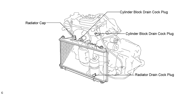
- NOTICE:
- Do not remove the radiator cap sub-assembly while the engine and radiator are still hot. Pressurized, hot engine coolant and steam may be released and cause serious burns.
Remove the radiator cap sub-assembly from the radiator assembly.
Loosen the radiator drain cock plug and 2 cylinder block drain cock plugs, then drain the coolant.
- HINT:
- Collect the coolant in a container and dispose of it according to the regulations in your area.
| 10. REMOVE COOL AIR INTAKE DUCT SEAL |
Remove the 7 clips and intake duct seal.
| 11. REMOVE V-BANK COVER SUB-ASSEMBLY |
Hold the front of the V-bank cover and raise it to disengage the 2 retainers on the front of the cover. Continue to raise the cover to disengage the retainer on the rear of the cover and remove the cover.
- NOTICE:
- Attempting to disengage both front and rear clips at the same time may cause the cover to break.
| 12. REMOVE AIR CLEANER INLET ASSEMBLY |
Remove the 2 bolts, clamp and air cleaner inlet.
| 13. REMOVE AIR CLEANER CAP SUB-ASSEMBLY |
Disconnect the 3 vacuum hoses.
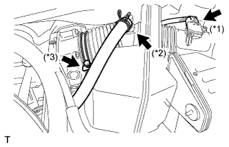
Disconnect the mass air flow meter connector (*1).
Disconnect the No. 2 ventilation hose (*2).
Disconnect the hose band (*3).
Disconnect the 3 bands, and remove the air cleaner cap sub-assembly.
| 14. REMOVE NO. 1 AIR CLEANER INLET |
Remove the bolt and No. 1 air cleaner inlet.
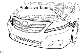
| 15. REMOVE FRONT BUMPER ASSEMBLY |
Put protective tape around the front bumper assembly.
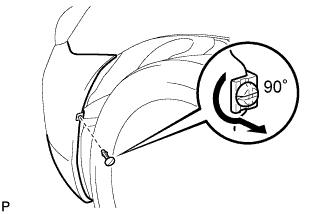
Using a screwdriver, turn the pin 90 degrees and remove the pin hold clip.
- HINT:
- Use the same procedure for the RH side and LH side.
Remove the 8 screws, 2 clips, 2 radiator grille protectors and bolt.
Disengage the 2 claws and disconnect the front bumper assembly as shown in the illustration.
- HINT:
- Use the same procedure for the RH side and LH side.
Disconnect each connector.
w/ TOYOTA Parking Assist-sensor System:
Disengage the clamp and disconnect the No. 1 ultrasonic sensor connector.
w/ Headlight Cleaner System:
Disconnect the headlight cleaner washer hose.
Remove the front bumper assembly.
| 16. REMOVE FRONT BUMPER ENERGY ABSORBER |
Disengage the 2 guides and remove the front bumper energy absorber from the front bumper reinforcement sub-assembly.
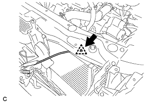
| 17. SEPARATE RADIATOR RESERVE TANK HOSE |
Separate the radiator reserve tank hose from the radiator assembly.
| 18. DISCONNECT RADIATOR INLET HOSE |
Separate the radiator inlet hose from the radiator assembly.
| 19. DISCONNECT RADIATOR OUTLET HOSE |
Separate the radiator outlet hose from the radiator assembly.
| 20. DISCONNECT NO. 1 OIL COOLER INLET HOSE (for Automatic Transaxle) |
Separate the No. 1 oil cooler inlet hose from the radiator assembly.
| 21. DISCONNECT NO. 1 OIL COOLER OUTLET HOSE (for Automatic Transaxle) |
Separate the No. 1 oil cooler outlet hose from the radiator assembly.
| 22. REMOVE RADIATOR SUPPORT UPPER |
Disconnect the horn connector.
Remove the 3 bolts and separate the hood lock assembly from the radiator support upper.
For LHD:
Remove the clamp and separate the hood lock control cable from the radiator support upper.
For RHD:
Remove the clamp and separate the hood lock control cable from the radiator support upper.
Remove the 5 bolts and radiator support upper.
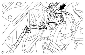
Remove the 3 clamps and connector.
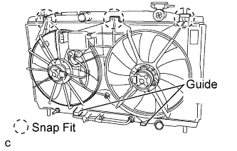
Release the 3 snap fits and lift the fan assembly with motor from the radiator.
| 24. REMOVE RADIATOR ASSEMBLY |
Remove the 4 bolts and separate the condenser assembly from the radiator assembly.
Remove the radiator assembly from the body.
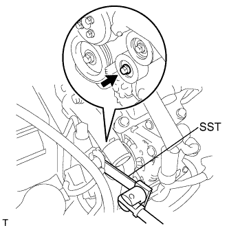
Using SST, release the belt tension by turning the belt tensioner counterclockwise, and remove the V-ribbed belt from the belt tensioner.
- SST
- 09249-63010
While turning the belt tensioner counterclockwise, align with its holes, and then insert the 5 mm bi-hexagon wrench into the holes to fix the V-ribbed belt tensioner.
| 26. REMOVE GENERATOR ASSEMBLY |
Remove the terminal cap.
Remove the nut and disconnect the wire harness from terminal B.
Disconnect the generator connector from the generator assembly.
Disconnect the connector from the compressor and magnetic clutch.
Disconnect the 2 wire harness clamps.
Remove the 2 bolts.
Remove the bolt from the cylinder block.
Disconnect the wire harness clamp and remove the generator assembly.
Remove the bolt and wire harness clamp stay.
Remove the bolt and bracket.
Remove the piping clamp from the No. 1 cooler refrigerant discharge hose and No. 1 cooler refrigerant suction hose.
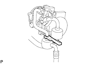
| 28. DISCONNECT NO. 1 COOLER REFRIGERANT DISCHARGE HOSE |
Remove the bolt and disconnect the No. 1 cooler refrigerant discharge hose from the compressor.
Remove the O-ring from the discharge hose sub-assembly.
- NOTICE:
- Seal the openings of the disconnected parts using vinyl tape to prevent entry of moisture and foreign matter.
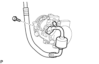
| 29. DISCONNECT NO. 1 COOLER REFRIGERANT SUCTION HOSE |
Remove the bolt and disconnect the No. 1 cooler refrigerant suction hose from the compressor.
Remove the O-ring from the cooler refrigerant suction hose.
- NOTICE:
- Seal the openings of the disconnected parts using vinyl tape to prevent entry of moisture and foreign matter.
| 30. REMOVE COMPRESSOR AND MAGNETIC CLUTCH |
Disconnect the magnetic clutch connector.
Remove the 4 bolts.
Remove the compressor and magnetic clutch.