Sfi System Fuel Pump Control Circuit
DESCRIPTION
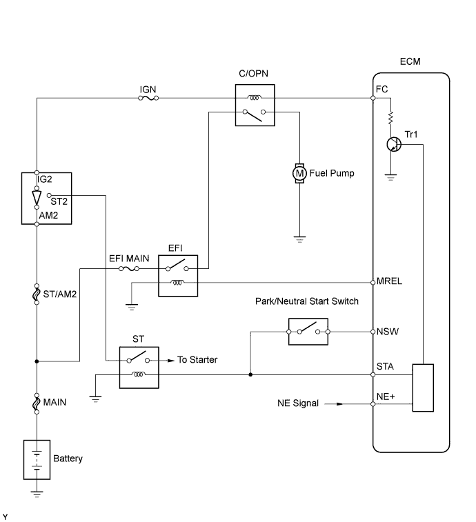
WIRING DIAGRAM
INSPECTION PROCEDURE
PERFORM ACTIVE TEST USING INTELLIGENT TESTER (OPERATE C/OPN RELAY)
CHECK ECM POWER SOURCE CIRCUIT
INSPECT ENGINE ROOM JUNCTION BLOCK (C/OPN RELAY)
INSPECT ECM (FC VOLTAGE)
INSPECT FUEL PUMP
CHECK HARNESS AND CONNECTOR (C/OPN RELAY - FUEL PUMP - BODY GROUND)
SFI SYSTEM - Fuel Pump Control Circuit |
DESCRIPTION
When the engine is cranked, the starter relay drive signal output from the STAR terminal of the ECM is input into the STA terminal of the ECM, and a NE signal generated by the crankshaft position sensor is also input into the NE+ terminal. Thus, the ECM interprets that the engine is cranked, and turns the transistor Tr1 in the ECM internal circuit ON. The current flows to the C/OPN (Circuit Opening) relay by turning the Tr1 ON. Then, the fuel pump operates.While the NE signal is input into the ECM, when the engine is running, the ECM turns the Tr1 on continuously.
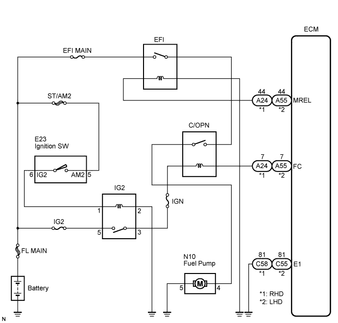
WIRING DIAGRAM
INSPECTION PROCEDURE
| 1.PERFORM ACTIVE TEST USING INTELLIGENT TESTER (OPERATE C/OPN RELAY) |
Connect the intelligent tester to the DLC3.
Turn the ignition switch to the ON position and turn the tester on.
Select the following menu items: Powertrain / Engine / Active Test / Fuel Pump / Speed.
Check whether the fuel pump operation sound occurs when performing the Active Test on the tester.
- OK:
- Fuel pump operating sound occurs.
| OK |
|
|
|
| PROCEED TO NEXT CIRCUIT INSPECTION SHOWN IN PROBLEM SYMPTOMS TABLE |
|
| 2.CHECK ECM POWER SOURCE CIRCUIT |
| | REPAIR OR REPLACE ECM POWER SOURCE CIRCUIT |
|
|
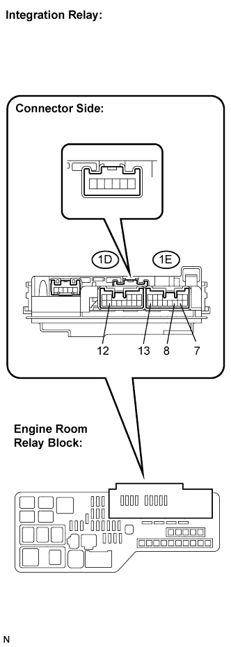
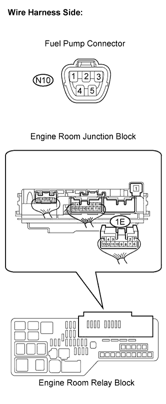
| 3.INSPECT ENGINE ROOM JUNCTION BLOCK (C/OPN RELAY) |
Remove the integration relay from the engine room relay block.
Inspect the C/OPN relay.
Measure the C/OPN relay resistance.
- Standard resistance:
Tester Connection
| Specified Condition
|
1E-7 - 1E-13
| 10 kΩ or higher
|
Below 1 Ω
(Apply battery voltage between terminals 1D-12 and 1E-8)
|
Reinstall the integration relay.
| | REPLACE ENGINE ROOM JUNCTION BLOCK |
|
|
| 4.INSPECT ECM (FC VOLTAGE) |
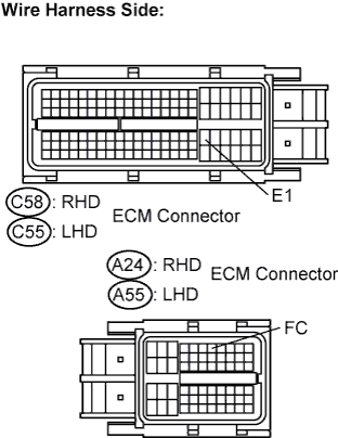
Disconnect the C58 (RHD) or C55 (LHD) and A24 (RHD) or A55 (LHD) ECM connectors.
Measure the voltage between the terminals.
- Standard voltage:
- RHD:
Tester Connection
| Specified Condition
|
FC (A24-7) - E1 (C58-81)
| 9 to 14 V
|
- LHD:
Tester Connection
| Specified Condition
|
FC (A55-7) - E1 (C55-81)
| 9 to 14 V
|
Reconnect the ECM connectors.
| | REPAIR OR REPLACE HARNESS OR CONNECTOR (ECM - BATTERY) |
|
|
| 6.CHECK HARNESS AND CONNECTOR (C/OPN RELAY - FUEL PUMP - BODY GROUND) |
Check the harness and the connectors between the engine room relay block and the fuel pump.
Disconnect the integration relay connector.
Disconnect the N10 fuel pump connector.
Measure the resistance.
- Standard resistance:
- Check for open:
Tester Connection
| Specified Condition
|
1E-13 - N10-4 (Fuel pump)
| Below 1 Ω
|
- Check for short:
Tester Connection
| Specified Condition
|
1E-13 or N10-4 (Fuel pump) - Body ground
| 10 kΩ or higher
|
Check the harness and the connectors between the fuel pump and body ground.
Disconnect the N10 fuel pump connector.
Measure the resistance.
- Standard resistance :
- Check for open:
Tester Connection
| Specified Condition
|
N10-5 (Fuel pump) - Body ground
| Below 1 Ω
|
Reconnect the integration relay connector.
Reconnect the fuel pump connector.
| | REPAIR OR REPLACE HARNESS OR CONNECTOR |
|
|