INSPECT PARK/NEUTRAL POSITION SWITCH ASSEMBLY
INSPECT TRANSMISSION CONTROL SWITCH
CHECK ECU TERMINAL VOLTAGE (STA TERMINAL)
CHECK HARNESS AND CONNECTOR (PARK/NEUTRAL POSITION SWITCH - TCM)
AUTOMATIC TRANSAXLE SYSTEM - Park / Neutral Position Switch Circuit |
DESCRIPTION
The park/neutral position switch detects the shift lever position and sends signals to the TCM.WIRING DIAGRAM
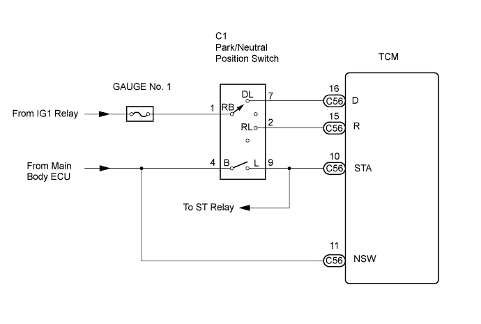
INSPECTION PROCEDURE
| DATA LIST |
- HINT:
- According to the Data List displayed on the intelligent tester, you can read the value of switches, sensors, actuators and other items without removing any parts. Reading the Data List as the first step in troubleshooting is one method to save labor time.
- NOTICE:
- In the table below, the values listed under "Normal Condition" are reference values. Do not depend solely on these reference values when deciding whether a part is faulty.
Warm up the engine.
Turn the ignition switch off.
Connect the intelligent tester to the DLC3.
Turn the ignition switch on.
Turn on the tester.
Enter the following items: "Powertrain / ECT / Data List".
According to the display on the tester, read "Data List".
Item Measurement Item/
Range (display)Normal Condition Diagnostic Note Neutral Position SW Signal PNP Switch Status/
ON or OFFShift lever position is;
P and N: ON
Except P and N: OFFWhen the shift lever position displayed on the intelligent tester differs from the actual position, adjustment of the PNP switch or the shift cable may be incorrect. Shift SW Status (R Range) PNP Switch Status/
ON or OFFShift lever position is;
R: ON
Except R: OFFWhen the shift lever position displayed on the intelligent tester differs from the actual position, adjustment of the PNP switch or the shift cable may be incorrect. Shift SW Status (P Range) PNP Switch Status/
ON or OFFShift lever position is;
P: ON
Except P: OFFWhen the shift lever position displayed on the intelligent tester differs from the actual position, adjustment of the PNP switch or the shift cable may be incorrect. Shift SW Status (N Range) PNP Switch Status/
ON or OFFShift lever position is;
N: ON
Except N: OFFWhen the shift lever position displayed on the intelligent tester differs from the actual position, adjustment of the PNP switch or the shift cable may be incorrect. Shift SW Status (D Range) PNP Switch Status/
ON or OFFShift lever position is;
D and S: ON
Except D and S: OFFWhen the shift lever position displayed on the intelligent tester differs from the actual position, adjustment of the PNP switch or the shift cable may be incorrect. Sports Mode Selection SW Sport Mode Select Switch Status/
ON or OFFShift lever position is;
S, "+" and "-": ON
Except S, "+" and "-": OFF-
| 1.INSPECT PARK/NEUTRAL POSITION SWITCH ASSEMBLY |
Disconnect the park/neutral position switch connector.
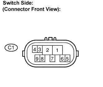 |
Measure the resistance according to the value(s) in the table below when the shift lever is moved to each position.
- Standard resistance:
Shift Position Tester Connection Specified Condition P 1 - 3 and 4 - 9 Below 1 Ω Except P 10 kΩ or higher R 1 - 2 Below 1 Ω Except R 10 kΩ or higher N 1 - 8 and 4 - 9 Below 1 Ω Except N 10 kΩ or higher D, S, "+" and "-" 1 - 7 Below 1 Ω Except D, S, "+" and "-" 10 kΩ or higher
|
| ||||
| OK | |
| 2.INSPECT TRANSMISSION CONTROL SWITCH |
Connect the park/neutral position switch connector.
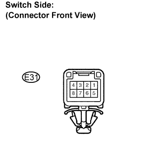 |
Disconnect the transmission control switch connector of the shift lock control unit assembly.
Measure the resistance according to the value(s) in the table below when the shift lever is moved to each position.
- Standard resistance:
Shift Position Tester Connection Specified Condition S, "+" and "-" 3 - 7 Below 1 Ω Except S, "+" and "-" 10 kΩ or higher
|
| ||||
| OK | |
| 3.CHECK ECU TERMINAL VOLTAGE (STA TERMINAL) |
Connect the transmission control switch connector of the shift lock control unit assembly.
 |
Measure the voltage according to the value(s) in the table below while cranking the engine.
- Standard voltage:
Tester Connection Specified Condition STA (C56-10) - Body ground 9 to 14 V
|
| ||||
| OK | |
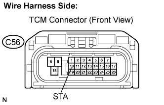
| 4.CHECK HARNESS AND CONNECTOR (PARK/NEUTRAL POSITION SWITCH - TCM) |
Disconnect the TCM connector.
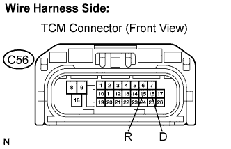 |
Turn the ignition switch on, and measure the voltage according to the value(s) in the table below when the shift lever is moved to each position.
- Standard voltage:
Shift Position Tester Connection Specified Condition R R (C56-15) - Body ground 10 to 14 V * Except R Below 1 V D D (C56-16) - Body ground 10 to 14 V Except D Below 1 V
- HINT:
- *: The voltage will drop slightly because the back up light is turned on.
|
| ||||
| OK | ||
| ||