Power Door Lock Control System Luggage Compartment Door Lock Circuit
DESCRIPTION
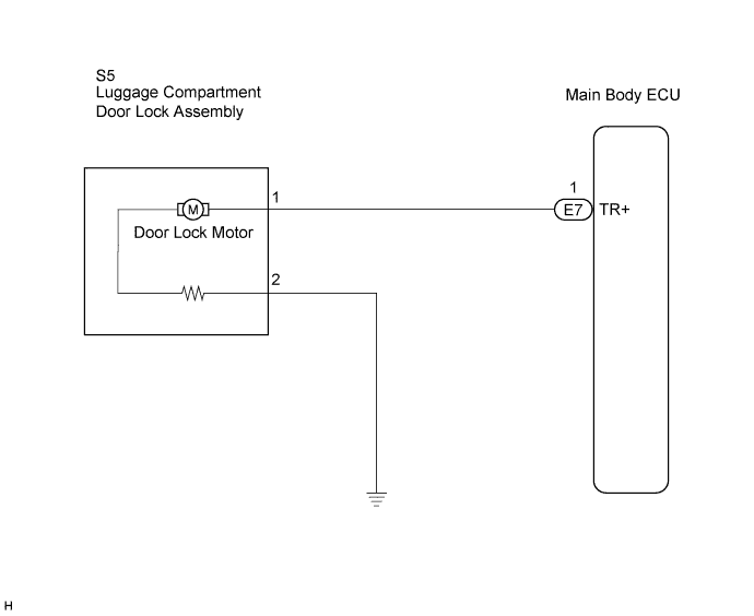
WIRING DIAGRAM
INSPECTION PROCEDURE
PERFORM ACTIVE TEST (LUGGAGE COMPARTMENT DOOR)
INSPECT LUGGAGE COMPARTMENT DOOR LOCK ASSEMBLY (DOOR LOCK MOTOR)
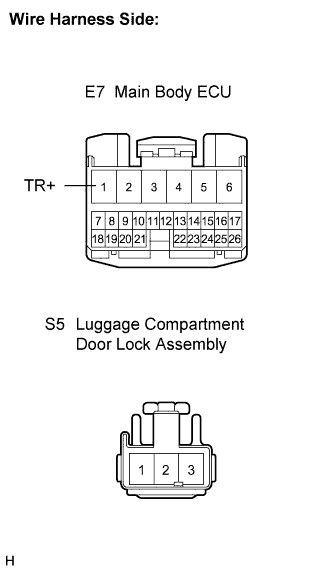
CHECK WIRE HARNESS (LUGGAGE COMPARTMENT DOOR LOCK - MAIN BODY ECU)
POWER DOOR LOCK CONTROL SYSTEM - Luggage Compartment Door Lock Circuit |
DESCRIPTION
The luggage compartment door lock motor is built into the luggage compartment door lock assembly.The main body ECU receives a luggage compartment door unlock signal from the wireless transmitter or electrical key switch*1 and operates the door lock motor.- *1: w/ Entry and Start System
WIRING DIAGRAM
INSPECTION PROCEDURE
| 1.PERFORM ACTIVE TEST (LUGGAGE COMPARTMENT DOOR) |
Select the ACTIVE TEST, use the intelligent tester to generate a control command, and then check that the door lock operates.
Main BodyItem
| Test Details
| Diagnostic Note
|
Trunk and Back-Door Open
| Operate luggage compartment door lock motor LOCK/UNLOCK
| -
|
- OK:
- Door lock is locked/unlocked.
| OK |
|
|
|
| PROCEED TO NEXT CIRCUIT INSPECTION SHOWN IN PROBLEM SYMPTOMS TABLE |
|
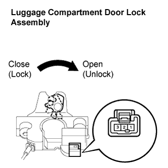
| 2.INSPECT LUGGAGE COMPARTMENT DOOR LOCK ASSEMBLY (DOOR LOCK MOTOR) |
Remove the luggage compartment door lock assembly.
Apply battery voltage and check operation of the door lock motor.
- OK:
Measurement Condition
| Specified Condition
|
Battery positive (+) → Terminal 1
Battery negative (-) → Terminal 2
| Unlock
|
| | REPLACE LUGGAGE COMPARTMENT DOOR LOCK ASSEMBLY |
|
|
| 3.CHECK WIRE HARNESS (LUGGAGE COMPARTMENT DOOR LOCK - MAIN BODY ECU) |
Disconnect the ECU connector.
Measure the resistance according to the value(s) in the table below.
- Standard resistance:
Tester Connection (Symbols)
| Condition
| Specified Condition
|
E7-1 (TR+) - S5-1
| Always
| Below 1 Ω
|
S5-1 - Body ground
| Always
| 10 kΩ or higher
|
S5-2 - Body ground
| Always
| Below 1 Ω
|
| | REPAIR OR REPLACE HARNESS OR CONNECTOR |
|
|
| OK |
|
|
|
| PROCEED TO NEXT CIRCUIT INSPECTION SHOWN IN PROBLEM SYMPTOMS TABLE |
|