Wiper And Washer System Wiper Motor Power Source Circuit
DESCRIPTION
WIRING DIAGRAM
INSPECTION PROCEDURE
INSPECT FUSE (WIP)
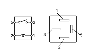
INSPECT IG1 RELAY
CHECK HARNESS AND CONNECTOR (WIPER MOTOR - BATTERY, BODY GROUND)
WIPER AND WASHER SYSTEM - Wiper Motor Power Source Circuit |
DESCRIPTION
This circuit provides power to the windshield wiper motor assembly.
WIRING DIAGRAM
INSPECTION PROCEDURE
Remove the WIP fuse from the instrument panel J/B.
Measure the resistance of the fuse.
- Standard resistance:
- Below 1 Ω
Remove the IG1 relay from the instrument panel J/B.
Measure the resistance of the relay.
- Standard resistance:
Tester Connection
| Condition
| Specified Condition
|
3 - 5
| Always
| 10 kΩ or higher
|
When battery voltage is applied to terminals 1 and 2
| Below 1 Ω
|
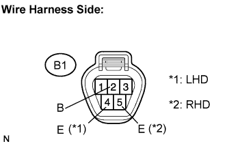
| 3.CHECK HARNESS AND CONNECTOR (WIPER MOTOR - BATTERY, BODY GROUND) |
Disconnect the B1 windshield wiper motor assembly connector.
Measure the voltage according to the value(s) in the table below.
- Standard voltage:
Tester Connection
| Switch Condition
| Specified Condition
|
B1-2 (B) - Body ground
| Ignition switch ON
| 10 to 14 V
|
Measure the resistance according to the value(s) in the table below.
- Standard resistance:
- for LHD:
Tester Connection
| Condition
| Specified Condition
|
B1-4 (E) - Body ground
| Always
| Below 1 Ω
|
- for RHD:
Tester Connection
| Condition
| Specified Condition
|
B1-5 (E) - Body ground
| Always
| Below 1 Ω
|
| | REPAIR OR REPLACE HARNESS OR CONNECTOR |
|
|
| OK |
|
|
|
| PROCEED TO NEXT CIRCUIT INSPECTION SHOWN IN PROBLEM SYMPTOMS TABLE |
|