Wiper And Washer System Headlight Cleaner Switch Circuit
DESCRIPTION
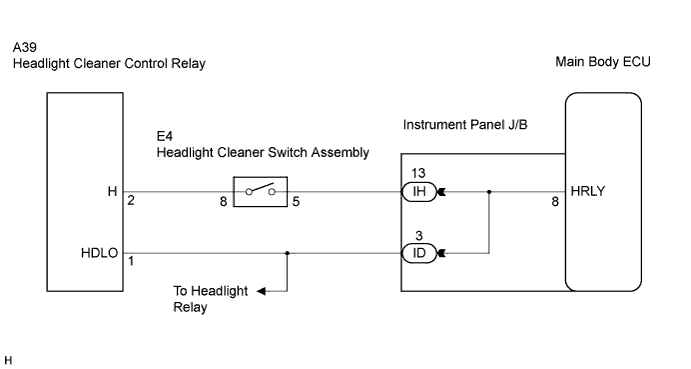
WIRING DIAGRAM
INSPECTION PROCEDURE
CHECK HEADLIGHT OPERATION
INSPECT HEADLIGHT CLEANER SWITCH ASSEMBLY
CHECK HARNESS AND CONNECTOR (CLEANER SWITCH - INSTRUMENT PANEL J/B, CLEANER RELAY)
CHECK WIRE HARNESS (CLEANER RELAY - INSTRUMENT PANEL J/B)
CHECK INSTRUMENT PANEL J/B
WIPER AND WASHER SYSTEM - Headlight Cleaner Switch Circuit |
DESCRIPTION
This circuit detects the conditions of the headlight cleaner switch.
WIRING DIAGRAM
INSPECTION PROCEDURE
| 1.CHECK HEADLIGHT OPERATION |
Check the headlight is operate normally.
- OK:
- The headlight operates normally.
| 2.INSPECT HEADLIGHT CLEANER SWITCH ASSEMBLY |
Remove the headlight cleaner switch assembly.
Measure the resistance according to the value(s) in the table below.
- Standard resistance:
Tester Connection
| Switch Condition
| Specified Condition
|
5 - 8
| ON
| Below 25 Ω
|
OFF
| 10 kΩ or higher
|
| | REPLACE HEADLIGHT CLEANER SWITCH ASSEMBLY |
|
|
| 3.CHECK HARNESS AND CONNECTOR (CLEANER SWITCH - INSTRUMENT PANEL J/B, CLEANER RELAY) |
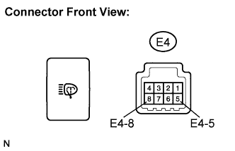
Disconnect the E4 headlight cleaner switch assembly connector.
Disconnect the A39 headlight cleaner control relay connector.
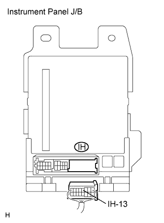
Disconnect the IH instrument panel J/B connector.
Measure the resistance according to the value(s) in the table below.
- Standard resistance:
Tester Connection
| Condition
| Specified Condition
|
E4-8 - A39-2 (H)
| Always
| Below 1 Ω
|
E4-8 - Body ground
| Always
| 10 kΩ or higher
|
E4-5 - IH-13
| Always
| Below 1 Ω
|
E4-5 - Body ground
| Always
| 10 kΩ or higher
|
| | REPAIR OR REPLACE HARNESS OR CONNECTOR |
|
|
| 4.CHECK WIRE HARNESS (CLEANER RELAY - INSTRUMENT PANEL J/B) |
Disconnect the ID instrument panel J/B connector.
Measure the resistance according to the value(s) in the table below.
- Standard resistance:
Tester Connection
| Condition
| Specified Condition
|
A39-1 (HDLO) - ID-3
| Always
| Below 1 Ω
|
| | REPAIR OR REPLACE HARNESS OR CONNECTOR |
|
|
| 5.CHECK INSTRUMENT PANEL J/B |
Measure the voltage according to the value(s) in the table below.
- Standard voltage:
Tester Connection
| Condition
| Specified Condition
|
IH-13 - Body ground
| Ignition switch ON and headlight dimmer switch OFF
| Below 1 V
|
IH-13 - Body ground
| Ignition switch ON and headlight dimmer switch ON
| 10 to 14 V
|
| | REPLACE INSTRUMENT PANEL J/B |
|
|
| OK |
|
|
|
| REPLACE PROCEED TO NEXT CIRCUIT INSPECTION SHOWN IN PROBLEM SYMPTOMS TABLE |
|