Starter -- Inspection |
| 1. INSPECT STARTER ASSEMBLY |
- CAUTION:
- Make sure to complete each of the following tests within 3 to 5 seconds to prevent the coil from burning out.
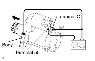
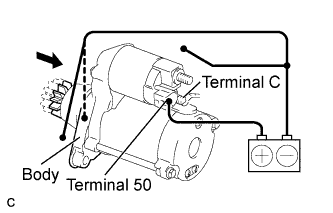
Perform a pull-in test:
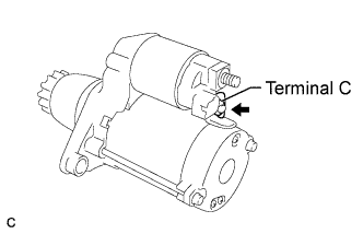
Connect the terminal C to the magnetic switch with the nut..
Connect the battery to the magnetic switch as shown in the illustration. Check that the clutch pinion gear moves outward.
If the clutch pinion gear does not move outward, replace the repair service starter kit.
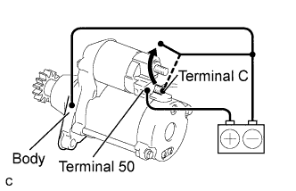
Perform a hold-in test:
Disconnect the negative (-) terminal lead from terminal C under the conditions for the pull-in test. Check that the pinion gear remains out.
If the clutch pinion gear moves inward, replace the repair service starter kit.
Inspect clutch pinion gear return:
Disconnect the negative (-) lead from the starter body. Check that the clutch pinion gear moves inward.
If the clutch pinion gear does not move inward, replace the repair service starter kit.
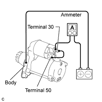
Perform a no-load performance test:
Connect the field coil wire to terminal C with the nut. Make sure that the lead is not grounded.
- Torque:
- 10 N*m{102 kgf*cm, 7 ft.*lbf}
Clamp the starter in a vise.
Connect the battery and an ammeter to the starter as shown in the illustration.
Check that the starter rotates smoothly and steadily with the clutch pinion gear extended. Check that the ammeter reads the specified current.
- Specified Current:
Condition Specified Condition at 11.5 V 90 A or less
| 2. INSPECT REPAIR SERVICE STARTER KIT |
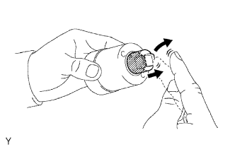
Check the plunger.
Push in the plunger and check that it returns quickly to its original position.
If necessary, replace the repair service starter kit.
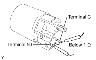
Check the pull-in coil for an open circuit.
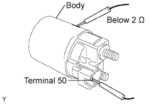
Using an ohmmeter, measure the resistance between terminals 50 and C.
- Standard Resistance:
Tester Connection Specified Condition Terminal 50 - Terminal C Below 1 Ω
Check the hold-in coil for an open circuit.
Using an ohmmeter, measure the resistance between terminal 50 and the switch body.
- Standard resistance:
Tester connection Specified condition Terminal 50 - Switch body Below 2 Ω
| 3. INSPECT STARTER ARMATURE ASSEMBLY |
- HINT:
- If these is no continuity between any segments, replace the starter armature assembly.
Check the commutator surface for dirt or burning.
If the surface is dirty or burnt, smooth the surface with 400-grit sandpaper or leather.
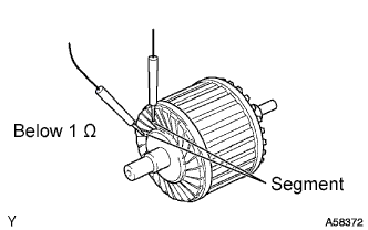
Check the commutator for an open circuit.
Using an ohmmeter, measure the resistance between the segments of the commutator.
- Standard Resistance:
Tester Connection Specified Condition Segment - Segment Below 1 Ω
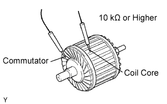
Using an ohmmeter, measure the resistance between the commutator and armature coil core.
- Standard Resistance:
Tester Connection Specified Condition Commutator - Armature coil core 10 kΩ or higher
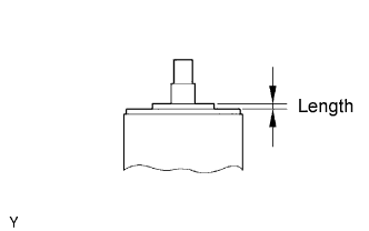
Using a vernier caliper, measure the commutator length.
- Standard length:
- 3.1 to 3.8 mm (0.122 to 0.149 in.)
- Maximum length:
- 3.8 mm (0.149 in.)
 |
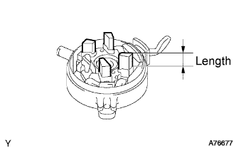
| 4. INSPECT STARTER COMMUTATOR END FRAME ASSEMBLY |
Check the brush length.
Using a vernier caliper, measure the brush length.
- Standard length:
- 4.0 to 9.0 mm (0.158 to 0.354 in.)
- Minimum length:
- 4.0 mm (0.158 in.)
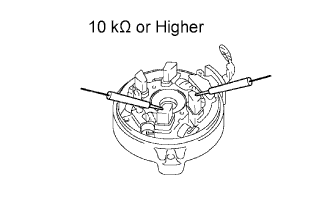
Check the resistance.
Using an ohmmeter, measure the resistance between the positive (+) and negative (-) brushes.
- Resistance:
- 10 kΩ or higher
| 5. INSPECT MOTOR TERMINAL STARTER KIT |
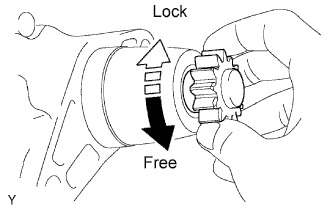
Check the starter clutch.
Rotate the clutch pinion gear counterclockwise and check that it turns freely. Try to rotate the clutch pinion gear clockwise and check that it locks.
If necessary, replace the motor terminal starter kit.