Cylinder Head -- Installation |
| 1. INSTALL CYLINDER HEAD GASKET |
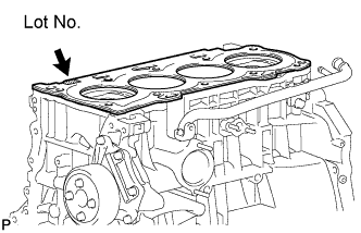
Place a new gasket on the cylinder block surface with the Lot No. stamp facing upward.
- NOTICE:
- Remove any oil from the contact surface.
- Make sure that the gasket is installed in the correct direction.
 |
| 2. INSTALL CYLINDER HEAD SUB-ASSEMBLY |
- HINT:
- The cylinder head bolts are tightened in 2 progressive steps.
Apply a light coat of engine oil to the bolt threads and the area beneath the bolt heads that come in contact with the washers.
Install the bolts and plate washers to the cylinder head.
- NOTICE:
- Do not drop the washers into the cylinder head.
Using several steps, uniformly install and tighten the 10 cylinder head set bolts and plate washers with a 10 mm bi-hexagon wrench in the order shown in the illustration.
- Torque:
- 70 N*m{714 kgf*cm, 52 ft.*lbf}
 |
Mark the front side of the cylinder head bolt with paint.
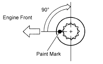 |
Retighten the cylinder head bolts 90° in the sequence shown in the illustration.
Check that the paint mark is now at a 90° angle to the front.
| 3. CONNECT ENGINE WIRE |
Connect the ground cable with the bolt.
- Torque:
- 8.4 N*m{86 kgf*cm, 74 in.*lbf}
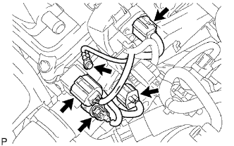 |
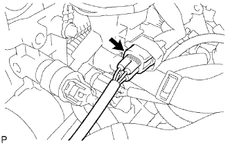
Connect the camshaft position sensor connector.
Connect the engine coolant temperature sensor connector.
Connect the engine oil pressure switch connector.
Connect the radio setting condenser connector.
| 4. CONNECT RADIATOR HOSE INLET |
Install the clamp and connect the radiator hose inlet.
 |
| 5. INSTALL NO. 2 CAMSHAFT BEARING |
Install the No. 2 camshaft bearing.
 |
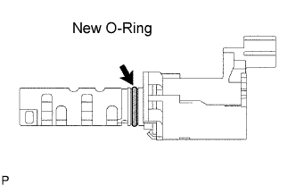
| 6. INSTALL CAMSHAFT TIMING OIL CONTROL VALVE ASSEMBLY |
Apply a light coat of engine oil to an O-ring of the camshaft timing oil control valve assembly sensor.
 |
Install the camshaft timing oil control valve assembly sensor with the bolt.
- Torque:
- 9.0 N*m{92 kgf*cm, 80 in.*lbf}
 |
Connect the camshaft timing oil control valve assembly sensor connector.
| 7. INSTALL CAMSHAFTS |
Apply a light coat of engine oil to the journal portion of the camshaft.
Place the 2 camshafts on the cylinder head with the No. 1 cam lobes facing the directions shown in the illustration.
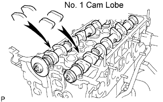 |
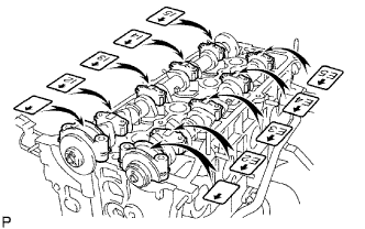
Examine the front marks and numbers, and check that the order is as shown in the illustration. Then install the bearing caps onto the cylinder head.
 |
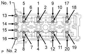
Apply a light coat of engine oil to the threads and under the heads of the bearing cap bolts.
Using several steps, uniformly tighten the 20 bearing cap bolts in the sequence shown in the illustration.
- Torque:
- No. 1 and No. 2 bearing cap:
- 30 N*m{301 kgf*cm, 22 ft.*lbf}
- No. 3 bearing cap:
- 9.0 N*m{92 kgf*cm, 80 in.*lbf}
 |
| 8. INSTALL CHAIN SUB-ASSEMBLY |
- HINT:
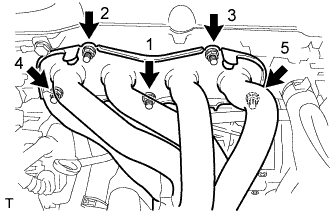
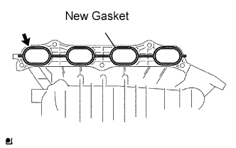
| 9. INSTALL EXHAUST MANIFOLD CONVERTER SUB-ASSEMBLY |
Install a new gasket onto the cylinder head.
Temporarily tighten the exhaust manifold converter with the 5 nuts.
Tighten the 5 nuts in the sequence shown in the illustration.
- Torque:
- 37 N*m{378 kgf*cm, 27 ft.*lbf}
 |
Connect the air-fuel ratio sensor connector.
 |
Install the exhaust manifold heat insulator with the 4 bolts.
- Torque:
- 12 N*m{122 kgf*cm, 9 ft.*lbf}
 |
| 10. INSTALL NO. 2 MANIFOLD STAY |
Install the stay with the bolt and nut.
- Torque:
- 44 N*m{449 kgf*cm, 32 ft.*lbf}
 |
| 11. INSTALL MANIFOLD STAY |
Install the stay with the bolt and nut.
- Torque:
- 44 N*m{449 kgf*cm, 32 ft.*lbf}
 |
| 12. INSTALL OIL LEVEL GAUGE GUIDE |
Apply a light coat of engine oil to a new O-ring and install it to the guide.
 |
Install the oil level gauge guide with the bolt.
- Torque:
- 9.0 N*m{92 kgf*cm, 80 in.*lbf}
| 13. INSTALL OIL LEVEL GAUGE SUB-ASSEMBLY |
| 14. INSTALL GENERATOR ASSEMBLY |
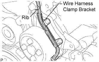
Confirm that the wire harness of the crankshaft position sensor is secured to the wire harness clamp bracket through the back of the rib of the timing chain cover.
 |
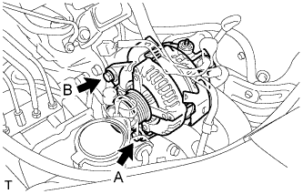
Install the generator assembly with the 2 bolts.
- Torque:
- Bolt A:
- 21 N*m{215 kgf*cm, 16 ft.*lbf}
- Bolt B:
- 52 N*m{530 kgf*cm, 38 ft.*lbf}
 |
Install the generator wire to terminal B with the nut.
- Torque:
- 9.8 N*m{100 kgf*cm, 87 in.*lbf}
 |
Install the clamp bracket with the bolt.
- Torque:
- 8.4 N*m{86 kgf*cm, 74 in.*lbf}
Attach the clamp and connect the generator connector to the generator.
| 15. INSTALL V-RIBBED BELT |
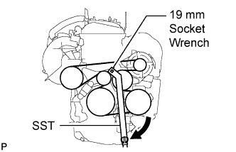
Using SST and 19 mm socket wrench, loosen the V-ribbed belt tensioner arm clockwise, then install the V-ribbed belt.
- SST
- 09216-42010
- NOTICE:
- Be sure to connect SST and the tools so that they are in line during use.
- When retracting the tensioner, turn it clockwise slowly for 3 seconds or more. Do not apply force rapidly.
- After the tensioner is fully retracted, do not apply force any more than necessary.
 |
After installing the V-ribbed belt, check that it fits properly in the ribbed grooves. Check to confirm that the belt has not slipped out of the grooves on the bottom of the crank pulley by hand.
| 16. INSTALL NO. 2 ENGINE MOUNTING BRACKET RH |
Install the 3 bolts and No. 2 mounting bracket RH.
- Torque:
- 52 N*m{531 kgf*cm, 38 ft.*lbf}
 |
| 17. INSTALL ENGINE MOVING CONTROL ROD SUB-ASSEMBLY |
Install the engine moving control rod with the 3 bolts.
- Torque:
- 64 N*m{653 kgf*cm, 47 ft.*lbf}
 |
Install the ground cable with the bolt.
- Torque:
- 8.4 N*m{85 kgf*cm, 74 in.*lbf}
 |
| 18. INSTALL NO. 2 ENGINE MOUNTING STAY RH |
Install the No. 2 mounting stay RH with the 2 bolts.
- Torque:
- 64 N*m{653 kgf*cm, 47 ft.*lbf}
 |
| 19. INSTALL FRONT EXHAUST PIPE ASSEMBLY |
- HINT:
| 20. INSTALL NO. 1 INTAKE MANIFOLD INSULATOR |
Install the intake manifold insulator onto the cylinder block.
 |
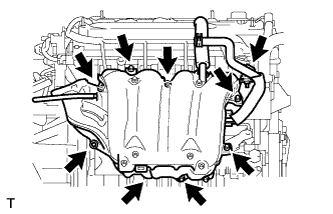
| 21. INSTALL INTAKE MANIFOLD |
Install a new gasket into the intake manifold.
 |
Install the intake manifold with the 5 bolts and 2 nuts.
- Torque:
- 30 N*m{306 kgf*cm, 22 ft.*lbf}
 |
Fit the union to check valve hose into the vacuum hose clamp.
Install the wire harness clamp.
Connect the camshaft timing oil control valve connector.
Connect the union to check valve hose to the brake booster.
| 22. INSTALL FUEL DELIVERY PIPE WITH INJECTOR |
Install 4 new insulators into the cylinder head.
 |
Install the 2 delivery pipe spacers onto the cylinder head.
Install the fuel delivery pipe together with the 4 fuel injectors, then temporarily tighten the 2 bolts.
- NOTICE:
- Be careful not to drop the fuel injectors when installing the fuel delivery pipe.
 |
Check that the fuel injector rotates smoothly.
If the fuel injector does not rotate smoothly, replace the O-ring.
Tighten the 2 bolts to the specified torque.
- Torque:
- 20 N*m{204 kgf*cm, 15 ft.*lbf}
 |
Connect the 4 fuel injector connectors.
 |
Install the 2 wire harness clamps.
| 23. CONNECT FUEL TUBE SUB-ASSEMBLY |
Push in the fuel tube connector to the fuel pipe until the connector makes a "click" sound.
- NOTICE:
- Check for damage or contamination on the connected part of the pipe.
- Check if the pipe and the connector are securely connected by trying to pull them apart.
 |
Install the No. 1 fuel pipe clamp.
 |
| 24. INSTALL THROTTLE BODY ASSEMBLY |
Install a new gasket onto the intake manifold.
 |
Connect the purge line hose to the throttle body.
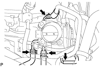 |
Connect the water by-pass hose to the throttle body.
Connect the No. 2 water by-pass hose to the throttle body.
Connect the No. 1 throttle body hose to the throttle body.
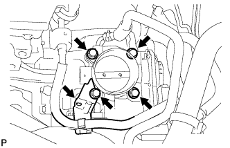
Install the throttle body and fuel pipe clamp with the 4 bolts.
- Torque:
- 30 N*m{305 kgf*cm, 22 ft.*lbf}
 |
Connect the fuel tube into the clamp.
Connect the throttle position sensor connector.
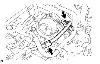 |
Connect the wire harness clamp.
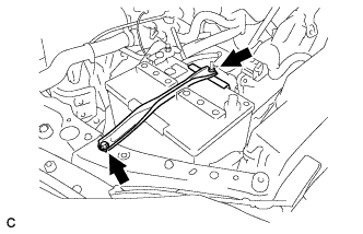
| 25. INSTALL BATTERY |
Install the battery and battery tray.
Install the battery clamp with the bolt and nut.
- Torque:
- Bolt:
- 9.0 N*m{92 kgf*cm, 80 in.*lbf}
- Nut:
- 3.5 N*m{36 kgf*cm, 31 in.*lbf}
 |
| 26. INSTALL AIR CLEANER CASE SUB-ASSEMBLY |
Install the air cleaner case with the 3 bolts.
- Torque:
- 5.0 N*m{51 kgf*cm, 44 in.*lbf}
 |
Connect the hose clamp.
| 27. INSTALL AIR CLEANER CAP SUB-ASSEMBLY |
Install the air cleaner filter element onto the air cleaner case.
Insert the hinges. Install the air cleaner cap sub-assembly with the 2 bolts.
 |
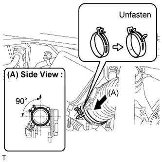
Align the matchmarks of the No. 1 air cleaner hose and throttle body, and then connect the air cleaner hose No. 1 to the throttle body and unfasten the No. 1 air cleaner hose clamp.
- NOTICE:
- Make sure that the hose clamp is at the correct angle.
 |
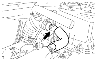
Connect the No. 2 ventilation hose to the air cleaner hose.
 |
Connect the purge line hose to the clamp (*1).
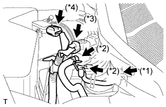 |
Connect the 2 purge VSV vacuum hoses (*2).
Connect the purge VSV connector (*3).
Connect the mass air flow meter connector (*4).
| 28. INSTALL AIR CLEANER INLET ASSEMBLY |
Install the air cleaner inlet with the 2 bolts.
- Torque:
- 5.0 N*m{51 kgf*cm, 44 in.*lbf}
 |
| 29. INSTALL COWL TOP PANEL OUTER SUB-ASSEMBLY |
Install the outer cowl top panel sub-assembly with the 4 bolts and 4 nuts.
- Torque:
- :
- N*m{ kgf*cm}
- Bolt:
- 5.0 N*m{51 kgf*cm, 44 in.*lbf}
- Nut:
- 85 N*m{867 kgf*cm, 62 ft.*lbf}
 |
| 30. INSTALL WINDSHIELD WIPER LINK ASSEMBLY |
- HINT:
| 31. CONNECT CABLE FROM NEGATIVE BATTERY TERMINAL |
- Torque:
- 6.9 N*m{70 kgf*cm, 61 in.*lbf}
| 32. ADD ENGINE OIL |
| 33. CHECK FOR FUEL LEAKS |
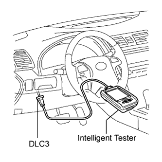
Check fuel pump operation.
Connect the intelligent tester to the DLC3.
Turn the ignition switch to the ON position and push the intelligent tester main switch on.
- NOTICE:
- Do not start the engine.
Select the following menus: Powertrain / Engine / Active Test / Control the Fuel Pump /Speed.
Check for pressure in the fuel inlet tube from the fuel line. Check that sound of fuel flowing in the fuel tank can be heard. If no sound can be heard, check the integration relay, fuel pump, ECM and wiring connector.
Check for fuel leaks.
Check that there are no fuel leaks anywhere on the system after performing maintenance. If there is a fuel leak, repair or replace parts as necessary.
Turn the ignition switch off.
Disconnect the intelligent tester from the DLC3.
| 34. ADD COOLANT |
Close the radiator drain cock plug and 2 cylinder block drain cock plugs.
- Torque:
- 13 N*m{130 kgf*cm, 9 ft.*lbf} for cylinder block drain cock plug
Slowly fill the radiator with TOYOTA Super Long Life Coolant (SLLC).
- Specified capacity:
- 6.2 liters (6.6 US qts, 5.5 lmp. qts)
- HINT:
- TOYOTA vehicles are filled with TOYOTA SLLC at the factory. In order to avoid damage to the engine cooling system and other technical problems, only use TOYOTA SLLC or similar high quality ethylene glycol based non-silicate, non-amine, non-nitrite, non-borate coolant with long-life hybrid organic acid technology (coolant with long-life hybrid organic acid technology consists of a combination of low phosphates and organic acids).
- Contact your TOYOTA dealer for further details.
Slowly pour coolant into the radiator reservoir tank until it reaches the FULL line.
Press the inlet and outlet radiator hoses several times by hand, and then check the level of the coolant.
If the coolant level is low, add coolant.
Install the radiator cap sub-assembly and reservoir tank cap.
Start the engine, and warm it up.
- HINT:
- Adjust the air conditioner set temperature to MAX (HOT).
Stop the engine, and wait until the engine coolant cools down.
Add engine coolant to the FULL line on the radiator reservoir.
| 35. CHECK FOR ENGINE COOLANT LEAKS |
 |
- NOTICE:
- Before performing each inspection, turn the A/C switch OFF.
- CAUTION:
- Do not remove the radiator cap while the engine and radiator are still hot. Pressurized, hot engine coolant and steam may be released and cause serious burns.
Fill the radiator with coolant and attach a radiator cap tester.
Warm up the engine.
Using a radiator cap tester, increase the pressure inside the radiator to 118 kPa (1.2 kgf*cm, 17 psi), and check that the pressure does not drop.
If the pressure drops, check the hoses, radiator and water pump for leaks. If no external leaks are found, check the heater core, cylinder block and cylinder head.
| 36. CHECK FOR ENGINE OIL LEAKS |
| 37. CHECK FOR EXHAUST GAS LEAKS |
| 38. INSPECT IGNITION TIMING |
Warm up the engine.
When using the intelligent tester:
Check the ignition timing.Connect the intelligent tester to the DLC3.
Enter DATA LIST MODE on the intelligent tester.
- Ignition timing:
- 8 to 12° BTDC at idle
- HINT:
- Refer to the intelligent tester operator's manual for help when selecting the DATA LIST.
 |
When not using the intelligent tester:
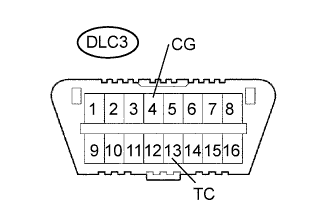
Check the ignition timing.Using SST, connect terminals 13 (TC) and 4 (CG) of the DLC3.
- SST
- 09843-18040
- NOTICE:
- Confirm the terminal numbers before connecting them. Connection with a wrong terminal can damage the engine.
- Turn off all electrical systems before connecting the terminals.
- Perform this inspection after the cooling fan motor is turned off.
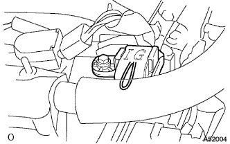
Remove the No. 1 engine cover.
Pull out the wire harness as shown in the illustration. Connect the clip of the timing light to the wire harness.
- NOTICE:
- Use a timing light which can detect the first signal.
- After checking, be sure to tape the wire harness.
Check the ignition timing at idle.
- Ignition timing:
- 8 to 12° BTDC at idle
- NOTICE:
- When checking the ignition timing, the transmission should be in neutral.
- HINT:
- After engine rpm is kept at 1,000 to 1,300 rpm for 5 seconds, check that it returns to idle speed.
Disconnect terminals 13 (TC) and 4 (CG) of the DLC3.
Check the ignition timing at idle.
- Ignition timing:
- 5 to 15° BTDC at idle
Confirm that the ignition timing moves to the advanced angle side when the engine rpm is increased.
Remove the timing light.
 |
| 39. INSPECT IDLE SPEED |
Warm up the engine.
|
When using the intelligent tester:
Check the idle speed.Connect the intelligent tester to the DLC3.
- HINT:
- Refer to the intelligent tester operator's manual for further details.
Enter DATA LIST MODE on the intelligent tester.
- Idle speed:
Item Specified Condition M/T 650 to 750 rpm A/T 610 to 710 rpm
- NOTICE:
- When checking the idle speed, the transmission should be in neutral.
- Check the idle speed with the cooling fan off.
- Switch off all accessories and air conditioning before connecting the intelligent tester.
When not using the intelligent tester:
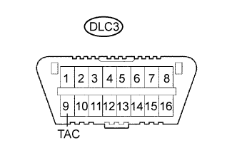
Check the idle speed.Using SST, connect the tachometer tester probe to terminal 9 (TAC) of the DLC3.
- SST
- 09843-18030
Check the idle speed.
- Idle speed:
Item Specified Condition M/T 650 to 750 rpm A/T 610 to 710 rpm
 |
| 40. INSPECT COMPRESSION |
Warm up and stop the engine.
Disconnect the injector connectors.
Remove the ignition coils.
Remove the spark plugs.
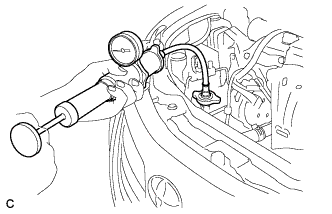
Check the cylinder compression pressure.
Insert a compression gauge into the spark plug hole.
Fully open the throttle.
While cranking the engine, measure the compression pressure.
- Compression pressure:
- 1.360 MPa (13.9 kgf/ cm2, 198 psi)
- Minimum pressure:
- 0.98 MPa (10 kgf/ cm2, 142 psi)
- Difference between each cylinder:
- 100 kPa (1.0 kgf/ cm2, 14 psi)
- NOTICE:
- Always use a fully charged battery to obtain an engine speed of 250 rpm or more.
- Check the other cylinders' compression pressure in the same way.
- This measurement must be done as quickly as possible.
If the cylinder compression is low, pour a small amount of engine oil into the cylinder through the spark plug hole and inspect again.
- HINT:
- If adding oil increases the compression, the piston rings and/or cylinder bore may be worn or damaged.
- If pressure stays low, a valve may be stuck or seated improperly, or there may be leakage in the gasket.
 |
| 41. INSPECT CO/HC |
Start the engine.
Run the engine at 2,500 rpm for approximately 180 seconds.
Insert the CO/HC meter testing probe at least 40 cm (1.3 ft) into the tailpipe during idling.
Immediately check CO/HC concentration at idle and/or 2,500 rpm.
- HINT:
- Complete the measuring within 3 minutes.
- Check regulations and restrictions in your area when performing 2 mode CO/HC concentration testing (engine check at both idle speed and at 2,500 rpm).
If the CO/HC concentration does not comply with regulations, troubleshoot in the order given below.
Check A/F sensor operation (CAMRY_ACV40 RM0000012OG006X_01_0001.html).
See the table below for possible causes, and then inspect and repair.
CO HC Problems Causes Normal High Rough idle - Faulty ignitions:
- Incorrect timing
- Fouled, shorted or improperly gapped plugs
- Incorrect valve clearance
- Leaky intake and exhaust valves
- Leaky cylinders
Low High Rough idle
(fluctuating HC reading)- Vacuum leaks:
- PCV hoses
- Intake manifold
- Throttle body
- Brake booster line
- Lean mixture causing misfire
High High Rough idle
(black smoke from exhaust)- Restricted air filter
- Plugged PCV valve
- Faulty SFI system:
- Faulty pressure regulator
- Defective engine coolant temperature sensor
- Defective MAF meter
- Faulty ECM
- Faulty injectors
- Faulty throttle position sensor
- Faulty ignitions:
| 42. INSTALL NO. 1 ENGINE COVER SUB-ASSEMBLY |
Install the engine cover with the 2 nuts.
- Torque:
- 9.0 N*m{92 kgf*cm, 80 in.*lbf}
 |
| 43. INSTALL FRONT FENDER APRON SEAL RH |
| 44. INSTALL ENGINE UNDER COVER LH |
| 45. INSTALL ENGINE UNDER COVER RH |
| 46. INSTALL FRONT WHEEL RH |
- Torque:
- 103 N*m{1,050 kgf*cm, 76 ft.*lbf}