Theft Deterrent System (W/ Entry And Start System) Security Horn Circuit
DESCRIPTION
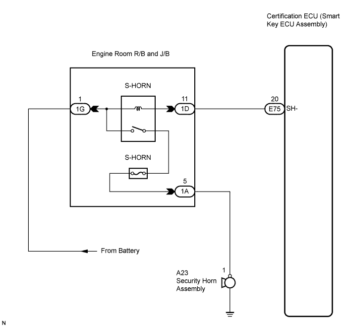
WIRING DIAGRAM
INSPECTION PROCEDURE
PERFORM ACTIVE TEST USING INTELLIGENT TESTER (SECURITY HORN)
INSPECT FUSE (S-HORN FUSE)
INSPECT ENGINE ROOM JUNCTION BLOCK ASSEMBLY (S-HORN RELAY)
CHECK HARNESS AND CONNECTOR (ENGINE ROOM JUNCTION BLOCK - BATTERY)
CHECK HARNESS AND CONNECTOR (INCLUDING SECURITY HORN ASSEMBLY)
CHECK HARNESS AND CONNECTOR (ENGINE ROOM J/B - CERTIFICATION ECU)
INSPECT SECURITY HORN ASSEMBLY
THEFT DETERRENT SYSTEM (w/ Entry and Start System) - Security Horn Circuit |
DESCRIPTION
When the theft deterrent system is changed from the armed state to the alarm sounding state, the certification ECU transmits a signal to cause the security horn to sound.
WIRING DIAGRAM
INSPECTION PROCEDURE
| 1.PERFORM ACTIVE TEST USING INTELLIGENT TESTER (SECURITY HORN) |
Connect the intelligent tester to the DLC3.
Turn the engine switch on (IG).
Press the intelligent tester main switch on.
Select the item below in the Active Test and then check that the indicator operates.
Smart (Certification ECU):Tester Display
| Test Part
| Control Range
| Diagnostic Note
|
Security Horn
| Security horn
| ON/OFF
| -
|
- OK:
- The security horn assembly sounds and stops correctly when operated through the intelligent tester.
| 2.INSPECT FUSE (S-HORN FUSE) |
Remove the S-HORN fuse from the engine room J/B.
Measure the resistance according to the value(s) in the table below.
- Standard resistance:
Terminal Connection
| Condition
| Specified Condition
|
S-HORN fuse
| Always
| Below 1 Ω
|
| 3.INSPECT ENGINE ROOM JUNCTION BLOCK ASSEMBLY (S-HORN RELAY) |
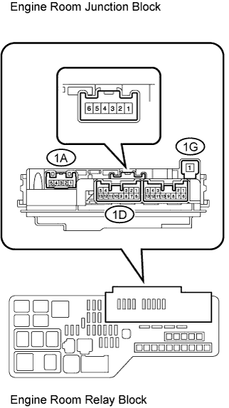
Remove the engine room J/B from the engine room R/B and J/B.
Connect a positive (+) lead from the battery to terminal 1G-1.
Connect a negative (-) lead from the battery to terminal 1D-11.
Measure the voltage according to the value(s) in the table below.
- Standard voltage:
Terminal Connection
| Condition
| Specified Condition
|
1A-5 - Body ground
| Always
| 10 to 14 V
|
| | REPLACE ENGINE ROOM JUNCTION BLOCK ASSEMBLY |
|
|
| 4.CHECK HARNESS AND CONNECTOR (ENGINE ROOM JUNCTION BLOCK - BATTERY) |
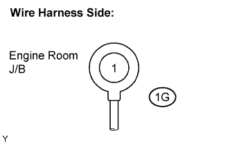
Disconnect the 1G J/B connector.
Measure the voltage according to the value(s) in the table below.
- Standard voltage:
Terminal Connection
| Condition
| Specified Condition
|
1G-1 - Body ground
| Always
| 11 to 14 V
|
| | REPAIR OR REPLACE HARNESS OR CONNECTOR |
|
|
| 5.CHECK HARNESS AND CONNECTOR (INCLUDING SECURITY HORN ASSEMBLY) |
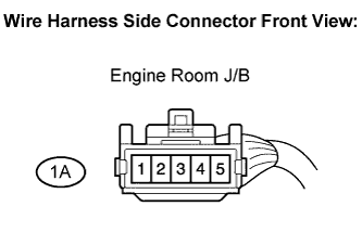
Disconnect the 1A J/B connector.
Connect a positive (+) lead from the battery to terminal 1A-5.
Connect a negative (-) lead from the battery to body ground.
Check the operation of the horn.
- Standard:
Measurement Condition
| Specified Condition
|
Battery positive (+) → Terminal 1A-5
| Horn sounds
|
Battery negative (-) → Body ground
|
| 6.CHECK HARNESS AND CONNECTOR (ENGINE ROOM J/B - CERTIFICATION ECU) |
Disconnect the E75 ECU connector.
Measure the resistance according to the value(s) in the table below.
- Standard resistance:
Terminal Connection
| Condition
| Specified Condition
|
E75-20 (SH-) - 1D-11
| Always
| Below 1 Ω
|
E75-20 (SH-) - Body ground
| Always
| 10 kΩ or higher
|
| | REPAIR OR REPLACE HARNESS OR CONNECTOR |
|
|
| OK |
|
|
|
| REPLACE CERTIFICATION ECU (SMART KEY ECU ASSEMBLY) |
|
| 7.INSPECT SECURITY HORN ASSEMBLY |
for RHD:
Remove the security horn assembly (CAMRY_ACV40 RM000001QZS004X.html).
Check the operation of the horn.
- Standard:
Measurement Condition
| Specified Condition
|
Battery positive (+) → Terminal 1
| Horn sounds
|
Battery negative (-) → Horn body
|
for LHD:
Remove the security horn assembly (CAMRY_ACV40 RM000001QZS004X.html).
Check the operation of the horn.
- Standard:
Measurement Condition
| Specified Condition
|
Battery positive (+) → Terminal 1
| Horn sounds
|
Battery negative (-) → Horn body
|
| OK |
|
|
|
| REPAIR OR REPLACE HARNESS OR CONNECTOR (ENGINE ROOM R/B AND J/B - SECURITY HORN ASSEMBLY) |
|